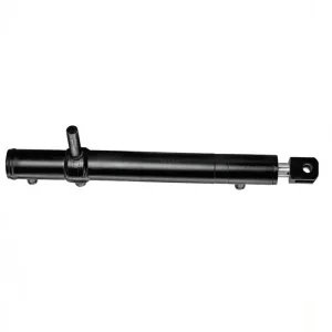
EP-Φ65xΦ35×607 Grain Tank Lifting Cylinder for Agricultural Machine
The EP-Φ65×Φ35×607 Grain Tank Lifting Cylinder for Agricultural Machine is a specialized hydraulic cylinder designed for grain tank lifting systems in agricultural machinery. It features a 65 mm bore, 35 mm rod diameter, and a 607 mm stroke, with an installation distance of 823 mm and a weight of 18 kg. Rated for a working pressure of 16.7 MPa and capable of withstanding up to 24.5 MPa, this cylinder ensures reliable operation under moderate load conditions typical in farming equipment. Its compact design and robust construction make it ideal for space-constrained applications while maintaining durability in field environments. This product adheres to industry standards, offering efficient performance for grain handling operations.
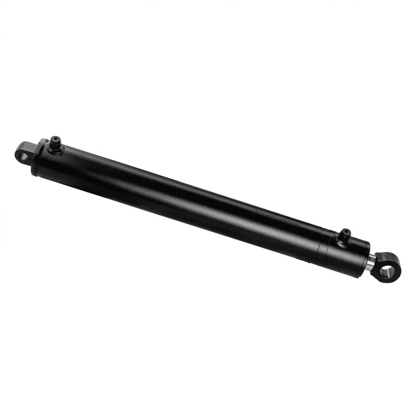
EP-Φ65xΦ35x607 Grain Tank Lifting Cylinder for Agricultural Machine
Model HCYY11112016 | Φ65×Φ35×607 | Working Pressure 16.7 MPa | Trip 607 mm | Weight 18 kg
Designed specifically for grain tank unloading systems on combine harvesters and grain harvesting machinery, this grain tank lifting cylinder provides reliable, high-force actuation of the grain tank cover or unloading auger positioning mechanism. Rated at 16.7 MPa working pressure with a 607 mm stroke and a compact 18 kg body weight, this grain tank lifting cylinder is an engineered solution for French and European agricultural OEM buyers and aftermarket replacement procurement teams.
Grain Tank Lifting Cylinder — Agricultural Hydraulic Series
The HCYY11112016 grain tank lifting cylinder addresses the specific demands of combine harvester grain tank mechanisms, where the grain tank lifting cylinder must repeatedly lift a loaded grain storage tank cover or position an unloading auger over many operating seasons without seal failure or rod surface degradation. The 607 mm stroke and 823 mm installation distance match the geometric requirements of standard European combine harvester grain tank lift arm assemblies, and the 24.5 MPa maximum withstand pressure delivers the burst safety margin required by agricultural machinery hydraulic system design standards applicable in France and across the EU.
Quick Reference
| Cylinder Model | HCYY11112016 |
| Specifications | Φ65×Φ35×607 mm |
| Working Pressure | 16.7 MPa |
| Max. Withstand Pressure | 24.5 MPa |
| Trip (Stroke) | 607 mm |
| Installation Distance | 823 mm |
| Weight | 18 kg |
| Cylinder Type | Double Acting Hydraulic Cylinder |
| Application | Grain Tank / Combine Harvester |
1. Technical Parameters — Grain Tank Lifting Cylinder HCYY11112016
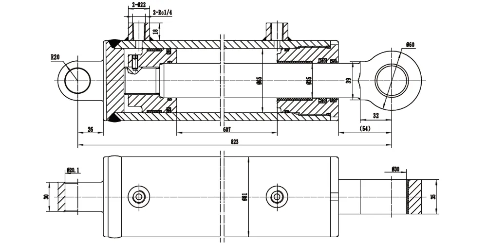
The following table presents the complete technical specification of the EP-Φ65xΦ35x607 grain tank lifting cylinder. All dimensional values are in millimetres (mm) unless otherwise indicated. For detailed dimensional drawings including port thread positions, clevis eye bore details, and end-of-stroke cushion specifications, contact our technical team.
| Parameter | Value | Notes |
|---|---|---|
| Cylinder Model | HCYY11112016 | Agricultural grain tank lifting series |
| Specifications | Φ65×Φ35×607 mm | Bore × Rod × Stroke |
| Working Pressure | 16.7 MPa | Rated continuous operating pressure |
| Maximum Withstand Pressure | 24.5 MPa | Burst / proof pressure rating |
| Trip (Stroke) | 607 mm | Full piston rod extension travel |
| Installation Distance | 823 mm | Pin-to-pin length in retracted position |
| Weight | 18 kg | Dry weight without hydraulic fluid |
| Bore Diameter | Φ65 mm | Cylinder barrel internal diameter |
| Rod Diameter | Φ35 mm | Hard chrome plated piston rod |
| Extension Force (at 16.7 MPa) | ≅ 55.4 kN | Theoretical bore-end force |
| Retraction Force (at 16.7 MPa) | ≅ 39.3 kN | Theoretical rod-end annular area force |
| Cylinder Type | Double Acting Hydraulic Cylinder | Positive force in both directions |
| Mounting Type | Clevis Eye (both ends) | Pin-mounted at barrel end and rod end |
| External Finish | Black industrial coating | Corrosion protection for agricultural field service |
| Application | Grain tank cover lift / auger pivot, combine harvester | Agricultural machinery hydraulic series |
2. About Our Φ65xΦ35x607 Grain Tank Lifting Cylinder
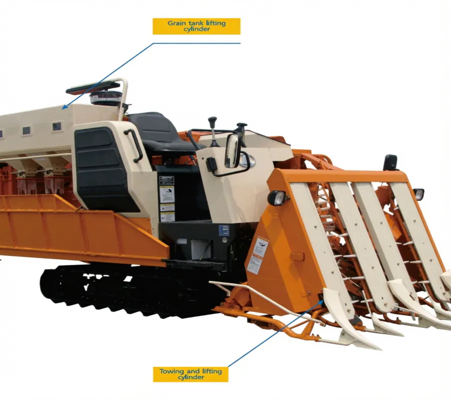
The grain tank lifting cylinder is a critical hydraulic actuator within the combine harvester grain management system. On a modern combine harvester, the grain storage tank is a large-volume hopper mounted above the machine body that accumulates threshed, cleaned grain during the harvesting pass. When the tank reaches capacity — or when the operator needs to transfer grain to a trailer running alongside — either the tank cover must be raised to allow overloading access, or the unloading auger must be pivoted from its transport position to its operating position. In many European combine harvester designs, the grain tank cover lift and the auger position actuator are both driven by a grain tank lifting cylinder matched to the combine's on-board hydraulic system. The HCYY11112016 grain tank lifting cylinder is designed and dimensioned for exactly this role: the Φ65 mm bore, Φ35 mm rod, and 607 mm stroke deliver the force and travel geometry required for combine harvester grain tank actuation at the 16.7 MPa working pressure typical of European combine hydraulic systems.
French grain farming — particularly in the major cereal-producing regions of Champagne-Ardenne, Centre-Val de Loire, Hauts-de-France, and Burgundy — relies heavily on large-scale combine harvesters with high-capacity grain tanks, often 9,000 to 14,000 litres on current-generation machines. At these tank sizes, the force required to lift a grain tank cover or swing a heavy unloading auger is considerable, and a grain tank lifting cylinder is the only actuator technology that can reliably deliver sustained high force in the compact installation envelope available inside and around the grain tank structure. The 607 mm stroke and 823 mm installation distance of this grain tank lifting cylinder match the arm geometry of combine harvester grain tank mechanisms across several common European machine models, and the double acting hydraulic cylinder configuration allows both powered opening and powered closing of the cover or auger, which is important in field conditions where wind resistance may oppose the return stroke of a gravity-return design.
The 16.7 MPa working pressure and 24.5 MPa burst pressure specification of this grain tank lifting cylinder conform to the hydraulic system design practice of European agricultural machinery manufacturers, who typically operate combine hydraulic circuits at 16 to 18 MPa and specify each hydraulic cylinder component with a 1.5:1 burst-to-working pressure safety ratio. French combine harvester operators using aftermarket replacement cylinders should verify that the replacement grain tank lifting cylinder meets these pressure ratings to maintain the safety and performance characteristics of the original machine design. The 18 kg unit weight contributes to the overall combine machine weight management — a consideration for transport on public French roads, where tractor and machinery train weight limits are enforced under French highway code (Code de la Route), and any reduction in grain tank mechanism component weight directly increases the available payload within the transport weight limit.
3. Five Key Advantages of the EP-Φ65xΦ35x607 Agricultural Grain Tank Lifting Cylinder
1. Agricultural Machinery Pressure Standards Compliance
The 16.7 MPa working pressure and 24.5 MPa maximum withstand pressure ratio (approximately 1.47:1) of this grain tank lifting cylinder aligns with the hydraulic cylinder design practice for European agricultural machinery, where EN 14540 and related ISO standards for agricultural machinery hydraulic systems specify hydraulic cylinder component pressure ratings. French agricultural machinery distributors and maintenance workshops dealing with CLAAS, John Deere, Case IH, and New Holland combine harvesters — all present in significant numbers across the French grain belt — will recognise this grain tank lifting cylinder pressure specification as standard for mid-range combine grain tank hydraulic actuators.
2. Compact 18 kg Weight for Machine Weight Budget Management
At 18 kg, this grain tank lifting cylinder achieves the lowest practical weight for a Φ65 mm bore unit of 607 mm stroke. On a combine harvester where multiple grain tank lifting cylinder units and other hydraulic actuators operate simultaneously — grain tank lift, unloading auger pivot, concave adjustment, reel drive, and cutter bar positioning — the cumulative weight contributes to the total machine unladen weight. French farmers transporting combines on public roads between parcelles are subject to French highway weight regulations, and every kilogram saved in hydraulic cylinder component weight is available for grain payload or simply keeps the machine within legal transport limits without additional road movement permit requirements.
3. Double-Acting Design for Positive Control in Field Conditions
Unlike single acting hydraulic cylinder designs that rely on gravity or spring return, this grain tank lifting cylinder provides positive hydraulic force in both extension and retraction directions. In the field, where wind loading may resist the return motion of a grain tank cover or where the auger must be retracted against friction in the pivot bearing under loaded conditions, the ability to apply hydraulic pressure to the return stroke eliminates the slow or incomplete return that gravity-return designs can exhibit. French farmers harvesting in the windy open landscapes of the Beauce or the Champagne plain particularly benefit from the positive hydraulic retraction that this grain tank lifting cylinder delivers in high-wind harvest conditions.
4. Hard-Chrome Rod for Multi-Season Agricultural Service Life
The Φ35 mm piston rod of this grain tank lifting cylinder is hard chrome plated to resist the abrasive and corrosive conditions of agricultural service. Combine harvesters operate in highly dusty, chaff-laden environments where the fine particles generated by threshing and separating operations settle on all exposed surfaces including the hydraulic cylinder rod. Without an adequately hard and thick chrome layer, these particles would act as an abrasive that scores the rod surface and progressively damages the rod seal on each stroke. The hard chrome specification of this grain tank lifting cylinder is selected to resist this abrasive wear through multiple harvest seasons without requiring rod replacement.
5. OEM Dimensional Compatibility for Direct Replacement
The Φ65 mm bore, Φ35 mm rod, 607 mm stroke, and 823 mm installation distance of this grain tank lifting cylinder are matched to the combine harvester grain tank mechanism dimensions used across several common European agricultural machine models. This dimensional compatibility allows direct fitment in machines where the original grain tank lifting cylinder has been damaged or has failed after extended service, without requiring modification to the machine mounting brackets or hydraulic hose connections. French agricultural machinery workshops handling combine harvester repairs during the off-season can stock this grain tank lifting cylinder as a universal replacement for multiple machine models within the same size class.
4. Working Principle: How the Grain Tank Lifting Cylinder Operates
The grain tank lifting cylinder operates on the principles of a conventional double acting hydraulic cylinder within the combine harvester's on-board hydraulic circuit. Hydraulic oil from the combine's main pump — driven mechanically from the engine or, in electric-hybrid machines, from a hydraulic power unit — is directed to either the bore end or the rod end of the grain tank lifting cylinder by a directional control valve operated from the cab. When the operator selects the "tank lift" or "auger deploy" function from the cab control panel, the directional valve routes pressurised oil to the bore-end chamber, pushing the piston and extending the rod. This mechanical extension pushes the grain tank cover open or pivots the unloading auger from its stowed transport position to its working discharge position. When the operator selects retract, pressurised oil is routed to the rod-end chamber, pushing the grain tank lifting cylinder piston back and retracting the rod to close the cover or return the auger to its transport position.
The relationship between hydraulic pressure and the force developed by this grain tank lifting cylinder is governed by basic hydraulic mechanics: extension force equals working pressure multiplied by bore-end piston area, and retraction force equals working pressure multiplied by the annular rod-end area (bore area minus rod area). At 16.7 MPa working pressure and a Φ65 mm bore (effective piston area approximately 3,318 mm²), the theoretical extension force of the grain tank lifting cylinder is approximately 55.4 kN — around 5.6 tonnes — which provides substantial margin above the force required to lift a typical combine grain tank cover, even when the cover itself carries accumulated grain dust and is subject to the weight of any residual grain that has collected on the upper surface during harvesting. The retraction force at the rod end is proportionally lower due to the smaller effective area, but is still sufficient to overcome any friction or wind load opposing the return stroke in the most common combine configurations encountered in French agricultural conditions.
A hydraulic cylinder seal is the critical interface that maintains the separation of the two pressure chambers within the grain tank lifting cylinder and prevents oil leakage past the rod to the exterior. In this grain tank lifting cylinder, the seal system comprises a composite piston seal set (sealing between piston and barrel bore), a rod seal assembly (sealing between piston rod and gland), and a wiper ring (preventing ingress of chaff and dust into the rod seal from the exterior). The wiper ring is particularly important in combine harvester applications, where the atmospheric environment around the cylinder contains very high concentrations of fine crop particles during harvesting. A correctly specified and maintained wiper ring on the hydraulic cylinder dramatically extends the life of the underlying rod seal by intercepting particles before they can work under the seal lip and score the chrome rod surface.
5. Materials and Construction Quality
Agricultural hydraulic cylinders operate in among the most demanding environments that any hydraulic cylinder component can encounter. The combine harvester environment combines high-frequency dust from chaff and grain processing, intermittent exposure to rain, morning dew condensation, and the corrosive chemistry of plant material residues and soil particles. A grain tank lifting cylinder that fails mid-harvest — particularly during the compressed French cereal harvest window of June to August — causes machine downtime that cannot easily be recovered. The material specification of the HCYY11112016 grain tank lifting cylinder addresses each of these environmental challenges.
The grain tank lifting cylinder barrel is produced from seamless cold-drawn steel tube with a precision-honed bore, achieving the surface finish tolerance required for long service life with the composite piston seal system. Cold-drawn tube production gives the barrel wall a consistent microstructure and tight dimensional tolerances that are difficult to achieve with hot-rolled alternatives, and the honed bore surface finish of Ra 0.2 to 0.4 μm provides the correct roughness for lubricating the piston seal without causing premature wear. The piston rod is solid alloy steel, precision-ground to Φ35 mm and hard chrome plated to a minimum deposit thickness of 0.015 mm with a hardness of 800–1,000 HV. This chrome specification resists the abrasive particles encountered in the combine's harvesting environment without requiring a heavier and more expensive rod cross-section. The end fittings — clevis eyes at both the barrel end and the rod end — are machined from medium-carbon steel to close dimensional tolerances on the clevis pin bore, ensuring correct pin fit and load transfer through the service life of the grain tank lifting cylinder.
The external finish visible on the product — a uniform black coating — is an industrial-grade protective system applied after all machining operations. The coating system consists of a conversion coat treatment followed by a black epoxy or enamel topcoat that provides corrosion protection appropriate for agricultural field service conditions. The coating must resist the chemical wash of fertiliser and crop protection product splatter, the mechanical abrasion of crop residues contacting the grain tank lifting cylinder barrel during harvesting, and the wet-dry cycling of field conditions through the French harvest season. For French agricultural machinery workshops looking for hydraulic cylinder component quality that holds up to seasonal off-field storage in unheated barns, the robust external coating of this grain tank lifting cylinder is an important quality differentiator compared to cheaper alternatives with thin paint finishes that rust within the first off-season storage period.
6. Grain Tank Lifting Cylinder Selection and Replacement Guide
Selecting the correct grain tank lifting cylinder for a specific combine harvester model begins with four measurable parameters taken from the machine's existing unit: bore diameter, rod diameter, stroke, and retracted installation distance. For the EP-HCYY11112016, these values are Φ65 mm bore, Φ35 mm rod, 607 mm stroke, and 823 mm installation distance. Any deviation in installation distance means the replacement grain tank lifting cylinder will not position the grain tank cover or unloading auger correctly within its mechanical travel range, even if bore, rod, and stroke all match. We provide a certified dimensional drawing with every grain tank lifting cylinder order so the installer can verify pin-hole positions against chassis brackets before removing the failed unit.
When evaluating a grain tank lifting cylinder replacement against the original equipment part, three factors determine functional equivalence: the pressure rating (the replacement grain tank lifting cylinder must equal or exceed the 16.7 MPa working pressure and 24.5 MPa withstand pressure of the original), the dimensional specification (the four parameters listed above), and the seal material (NBR or FKM, matched to the hydraulic fluid type specified by the combine manufacturer). A grain tank lifting cylinder that satisfies all three criteria is a valid hydraulic cylinder component substitute for the original and maintains the machine's type-approval safety characteristics.
French agricultural workshops procuring a grain tank lifting cylinder for multi-brand combine fleets should note that while several European combine manufacturers use similar bore and stroke dimensions in their grain tank mechanisms, installation distances and clevis pin bore diameters often differ between brands and model years. As a specialist grain tank lifting cylinder manufacturer, we maintain a cross-reference database of common combine harvester grain tank cylinder dimensions and can confirm compatibility before order placement. Contact our grain tank lifting cylinder manufacturer technical team with the machine make, model year, and grain tank mechanism dimensions for a confirmed cross-reference.
7. Regulatory and Standards Framework: France and Europe
Agricultural machinery sold and operated in France must comply with a specific regulatory and standards framework that spans EU-level directives, European harmonised standards, and French national regulations. Hydraulic cylinder components used in agricultural machinery — including grain tank lifting cylinders — are subject to this framework both as components of the complete machine type-approval process and as aftermarket replacement parts that must maintain the safety characteristics of the original machine.
At the EU level, agricultural tractors and self-propelled machinery including combine harvesters are subject to EU Regulation 167/2013 on type-approval of agricultural and forestry vehicles (replacing the former Machinery Directive 2006/42/EC framework for these vehicle types from 2016 onwards). Under this regulation, complete machines including their hydraulic systems must be type-approved by a notified body (in France, UTAC or Bureau Veritas Certification are the principal type-approval bodies for agricultural vehicles). Hydraulic system requirements within type-approved combine harvesters are specified by the machine manufacturer as part of the type-approval technical dossier, and any replacement hydraulic cylinder component must meet the pressure rating, dimensional, and material specifications documented in that dossier. Specifically, ISO 4413 (Hydraulic fluid power — General rules and safety requirements for systems and their components) and EN 14540 (Agricultural machinery — Hydraulic hoses, hydraulic systems) provide the technical standards framework within which agricultural hydraulic components must be designed and specified.
In France, the CNAM (Caisse Nationale d'Assurance Maladie) and ANSES (Agence Nationale de Sécurité Sanitaire) have issued guidance on agricultural machinery safety, and the MSA (Mutualité Sociale Agricole — the French agricultural social security and occupational safety body) publishes technical notes on combine harvester safety including hydraulic system maintenance. French agricultural machinery service workshops (ateliers agricoles) undertaking maintenance or repair of combine harvesters are subject to French workshop safety regulations under Code du Travail for machinery maintenance, and any grain tank lifting cylinder replacement must be documented in the machine maintenance log. For German market applications, the DIN EN ISO 4413 standard applies directly. For UK applications post-Brexit, PSSR 2000 (Pressure Systems Safety Regulations) applies to agricultural hydraulic systems, requiring inspection and documentation of pressure-rated components. For North American markets, SAE International standards for agricultural machinery hydraulics (SAE J2547 series) apply.
8. Application Scenarios
The EP-Φ65xΦ35x607 grain tank lifting cylinder serves multiple roles within the grain harvesting machinery hydraulic system. While the primary application is the grain tank cover or auger actuation on combine harvesters, the dimensional specification also suits several related agricultural machine applications where a compact, 607 mm stroke grain tank lifting cylinder with moderate bore is required.
Combine Harvester Grain Tank Cover Actuator
The primary application of this grain tank lifting cylinder is the grain tank cover lift on combine harvesters. When the operator signals grain tank overfill or initiates a tank-to-trailer transfer by opening the tank cover, this grain tank lifting cylinder extends to raise the cover from its transport-closed position to the open position. The 607 mm stroke provides the travel angle needed for the cover to fully clear the grain tank opening on typical European combine designs. In French cereal-growing regions where grain transfer at field headlands is a standard practice, this mechanism is operated many times per day during peak harvest periods, making durability of the grain tank lifting cylinder a critical operational requirement.
Unloading Auger Pivot Drive
Many combine harvesters use a grain tank lifting cylinder to swing the unloading auger from its transport position (folded alongside the grain tank) to its working position (extended outward at roughly 90 degrees to the machine body) in preparation for grain transfer to a chaser bin or trailer. The 823 mm installation distance and 607 mm stroke match the pivot geometry of unloading auger swing mechanisms on several common combine models available in France. A reliable grain tank lifting cylinder on this mechanism is essential for the grain transfer efficiency that French contract harvesting operators depend on to maintain their machine utilisation rates during the compressed harvest window.
Grain Cart and Transfer Wagon Lift
Grain carts and self-propelled grain transfer wagons used to shuttle grain from the combine to on-road grain trailers at field boundaries use a grain tank lifting cylinder or equivalent hydraulic actuator to raise the cart's auger discharge arm or to open the cart's spreading hood. The specification of the HCYY11112016 grain tank lifting cylinder — with its 16.7 MPa working pressure and 607 mm stroke — is compatible with grain cart auxiliary hydraulic systems typically operating from tractor remote hydraulics at 17 to 20 MPa. French farmers using large grain carts in the open-field conditions of the Beauce or the Plaine de Versailles benefit from the positive two-direction control that the double acting configuration provides for cart hood management in windy field conditions.
Cereal Processing Elevator and Conveyor Gate
On-farm cereal grain handling installations — including bucket elevators, auger conveyors, and grain-cleaning machines used in French farm-storage facilities (séchoirs and silos à plat) — use small hydraulic actuators to control flow-diversion gates, inspection hatches, and access doors in grain flow paths. The compact 18 kg weight and double acting configuration of this grain tank lifting cylinder make it a practical hydraulic cylinder component for these stationary plant applications, where a hydraulic power unit can be used to operate multiple gates from a central control panel during grain intake or out-loading operations at French cereal farms.
Seed Drill and Fertiliser Spreader Folding
Wide-span seed drills and centrifugal fertiliser spreaders with folding wing sections use hydraulic cylinders to fold the wings for road transport and unfold them for field operation. The Φ65 mm bore of this grain tank lifting cylinder provides a useful force level for folding the wing sections against their own weight and the resistance of the linkage geometry in mid-span wing designs. French arable farmers operating wide-span seed drills of 4 to 6 metres working width — common on the large cultivated blocks of the Centre-Val de Loire and Hauts-de-France regions — may find that the dimensional specification of this grain tank lifting cylinder suits their drill wing fold actuator as a direct replacement or upgrade from original components.
9. Grain Tank Lifting Cylinder Maintenance and Seasonal Service for Agricultural Applications
Agricultural hydraulic cylinders have a seasonal use pattern that differs significantly from industrial hydraulic cylinders in continuous-duty service. This grain tank lifting cylinder on a French combine harvester may operate for only 200 to 400 hours per year during the harvest season, then stand idle for nine or more months during the off-season. This seasonal pattern creates specific maintenance requirements that are often overlooked by agricultural machinery operators focused on the intensive harvest period rather than the quieter winter off-season.
The most important off-season maintenance task for this grain tank lifting cylinder is rod protection. When the grain tank lifting cylinder is retracted for transport and storage, the hard chrome rod is exposed to atmospheric corrosion in the annular gap between the rod wiper and the barrel end cap. In French agricultural conditions — where farm buildings range from well-maintained modern machine halls to older open-sided equipment stores in regions like Normandy and Brittany — the humidity and salt-laden coastal air can cause surface rust on the chrome rod within a single off-season storage period if the rod is not properly protected. A light film of hydraulic oil or a rod corrosion inhibitor applied to the exposed rod surface before storage — and wiped off before the next season's first operation — prevents this corrosion and avoids the seal damage that pitted or rusted rod surfaces cause when the wiper ring contacts the damaged chrome surface. The hydraulic cylinder component seal kit of this grain tank lifting cylinder (comprising the piston seal set, rod seal assembly, and wiper ring) should be inspected at the start of each harvest season and replaced if any sign of wear, swelling, or chemical degradation is found. The cost of a grain tank lifting cylinder seal kit is small compared to the cost of a combine harvester breakdown mid-harvest caused by an internal seal failure that routes pressurised oil across the piston without moving it.
Hydraulic fluid management is equally important for long grain tank lifting cylinder service life. Agricultural hydraulic oil should be changed every two to three seasons or every 1,000 operating hours — whichever comes first — with a filter change at each oil change. Contaminated hydraulic oil is the primary driver of premature grain tank lifting cylinder seal wear in agricultural applications, as fine particles from oil degradation and metal wear in the pump and valve circuits circulate through the cylinder and score the bore and rod surfaces, creating leak paths that worsen progressively. French agricultural co-operatives offering shared machinery services — CUMA (Coopératives d'Utilisation de Matériel Agricole) — that operate combine harvesters used by multiple members should maintain a specific hydraulic oil change log for each machine to ensure all member farms benefit from correctly maintained hydraulic systems throughout the shared equipment service life.
10. About Us — Grain Tank Lifting Cylinder Manufacturer
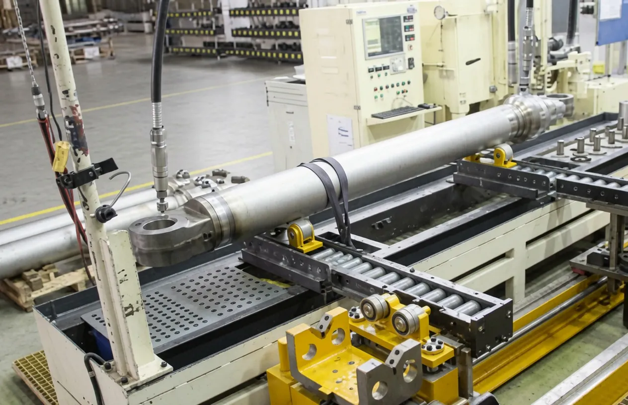
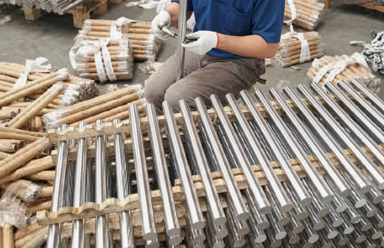
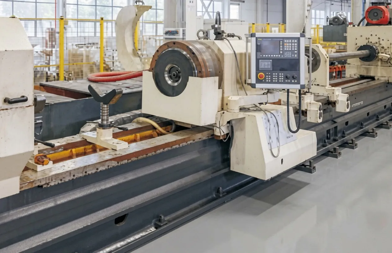
As a specialist grain tank lifting cylinder manufacturer, our hydraulic cylinder manufacturing group designs and produces a comprehensive range of agricultural hydraulic cylinders, forklift hydraulic cylinders, and industrial hydraulic actuators. The production facility operates under ISO 9001:2015 quality certification with CNC turning centres, deep-hole barrel drilling, precision honing lines, hard chrome plating, and automated hydraulic pressure testing equipment. We supply OEM agricultural machinery assemblers, aftermarket replacement parts distributors, and agricultural machinery service workshops across France, Germany, the United Kingdom, and global B2B markets.
WorkShop
11. Related Products — Complete Agricultural Hydraulic System
The grain tank lifting cylinder is one hydraulic cylinder component in a complete agricultural machine hydraulic system. We supply complementary hydraulic actuators and components that integrate with this grain tank lifting cylinder, enabling French and European agricultural machinery buyers to source their complete hydraulic cylinder component needs from a single technically consistent supplier.
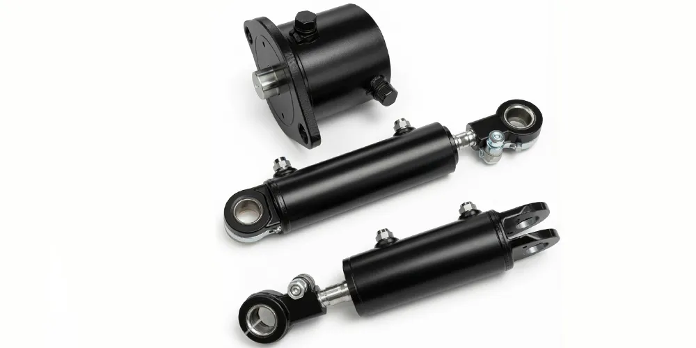
กระบอกเอียง
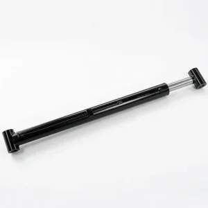
Our tilt cylinder range complements the grain tank lifting cylinder in agricultural machinery applications where both lift and tilt actuation are required. For combine harvester cutter bar tilt control, header angle adjustment, and grain ramp deflector positioning, the tilt cylinder from the same product range ensures dimensional and pressure compatibility with the same hydraulic system, simplifying maintenance parts management for French agricultural workshops.
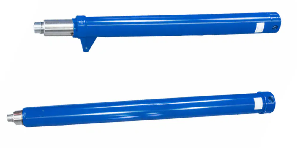
กระบอกยกของรถยก
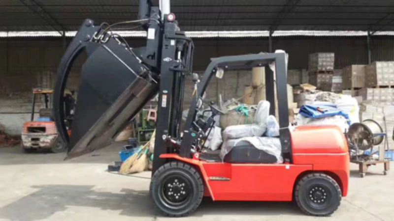
Our forklift lifting cylinder series uses the same precision barrel, rod, and seal manufacturing standards as the grain tank lifting cylinder, offering French agricultural businesses and co-operative CUMA operations that also maintain warehouse and loading-bay forklifts a consistent quality source for hydraulic cylinder replacement across both their field machinery and their materials handling equipment.
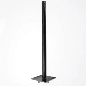
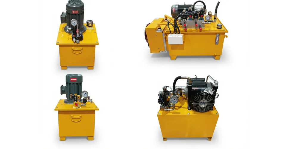
Hydraulic Pump Station
For stationary agricultural grain handling installations where a tractor remote hydraulic supply is not available, our hydraulic pump station series provides the pressurised oil source needed to operate the grain tank lifting cylinder and other hydraulic actuators at the 16.7 MPa working pressure. Electric motor driven pump stations with reservoir, filter, and pressure control are available in configurations matched to the flow and pressure requirements of single or multiple cylinder installations in French farm grain storage facilities.
Frequently Asked Questions
Editor: PXY