
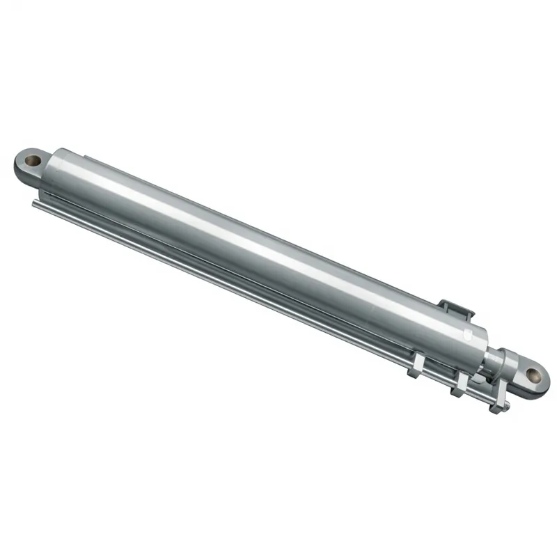
EP-Φ280×Φ160×2200 Lifting Hydraulic Cylinder For Crawler Crane
The EP-Φ280×Φ160×2200 is a large-bore, long-stroke lifting hydraulic cylinder designed for the main boom elevation circuit of crawler cranes and equivalent heavy lifting machinery. At Φ280 mm bore, this lifting hydraulic cylinder generates a push force of approximately 1,950 kN at 31.5 MPa working pressure — sufficient to elevate the main boom structure and suspended load of a mid-to-large capacity crawler crane through its full working arc. The 2200 mm stroke and 3000 mm installation distance correspond to the spatial requirements of boom-luffing cylinder arrangements on crawler cranes in the 100 to 500-tonne lift capacity class, which are the dominant heavy lifting machines used in French nuclear power plant maintenance, offshore wind turbine installation, large bridge construction, and refinery turnaround projects.
Crawler Crane Cylinder Series
EP-Φ280×Φ160×2200 Lifting Hydraulic Cylinder For Crawler Crane
A heavy-duty single-acting or double-acting lifting hydraulic cylinder engineered for crawler crane boom elevation circuits and large-capacity lifting hydraulic cylinder applications in construction, civil engineering, and energy infrastructure projects. Model HCYY11112018, Φ280×Φ160×2200 mm, rated at 31.5 MPa working pressure and 40 MPa maximum withstand pressure, 2200 mm stroke, 3000 mm installation distance, 1003 kg. Trusted by crawler crane manufacturers, heavy lifting contractors, and OEM engineering procurement teams across France and the European construction equipment market.
Key Technical Facts
1. Technical Specifications — EP-Φ280×Φ160×2200 Crawler Crane Lifting Hydraulic Cylinder
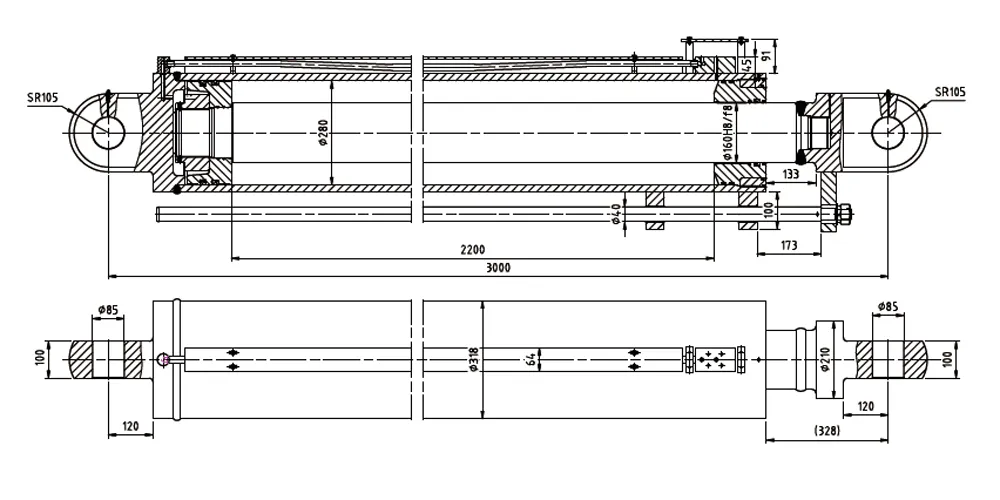
Model: HCYY11112018. Specification: Φ280 × Φ160 × 2200 (bore × rod × stroke, all in mm). Application: crawler crane boom luffing (lifting) circuit.
| Parameter | Value | Notes |
|---|---|---|
| Cylinder Model | HCYY11112018 | OEM part number, crawler crane cylinder series |
| Specification | Φ280 × Φ160 × 2200 | Bore Φ280 mm, rod Φ160 mm, stroke 2200 mm |
| Working Pressure | 31.5 MPa | Rated continuous operating pressure (315 bar) for crawler crane luffing circuit |
| Maximum Withstand Pressure | 40 MPa | Static proof pressure (400 bar); safety factor 1.27 above working pressure |
| Stroke (Trip) | 2200 mm | Total rod travel from fully retracted to fully extended position |
| Installation Distance | 3000 mm | Pin-to-pin center distance at installation reference position |
| Weight | 1003 kg | Unit weight; specialized lifting rigging required for installation |
| Push Force at Working Pressure | Approx. 1,939 kN | π × 140² mm² × 31.5 MPa = 1,939 kN (full bore area) |
| Pull Force at Working Pressure | Approx. 1,305 kN | π × (140² − 80²) mm² × 31.5 MPa = 1,305 kN (rod-end annular area) |
| Cylinder Type | Double-acting hydraulic cylinder | Active hydraulic control in both boom-up (extend) and boom-down (retract) directions |
| Mounting | Trunnion pin mounting with lateral guide rail | Guide rail feature accommodates angular change through full luffing arc; prevents lateral buckling |
| Application | Crawler crane boom luffing cylinder | 100–500 tonne capacity crawler cranes; major civil, nuclear, industrial construction |
2. What Is a Crawler Crane Lifting Hydraulic Cylinder?
A crawler crane lifting hydraulic cylinder is a large-bore, high-pressure hydraulic actuator that controls the elevation angle of the main boom assembly on a crawler crane. The boom luffing circuit — the hydraulic system responsible for raising and lowering the entire boom from its minimum working angle (typically 20 to 30 degrees from horizontal) to its maximum working angle (75 to 82 degrees) — relies on one or two lifting hydraulic cylinders to provide the enormous moment force required to move the boom through this arc while simultaneously supporting the weight of the suspended load. At Φ280 mm bore and 31.5 MPa working pressure, the bore area of 61,575 mm² generates an extension (push) force of approximately 1,939 kN — nearly 200 tonnes of hydraulic lifting force — available for boom luffing under the most demanding lifting conditions encountered on French construction and industrial sites.
The lifting hydraulic cylinder in a crawler crane differs fundamentally from the lifting hydraulic cylinder in aerial work platforms or forklift masts in three key respects. First, the load is indirect: the lifting hydraulic cylinder does not directly lift the suspended load but instead controls the boom angle, and the suspended load generates a variable bending moment at the boom pivot point that the cylinder must resist through the moment arm of its attachment point on the boom. Second, the lifting hydraulic cylinder operates at a changing geometric advantage as the boom angle changes — the effective cylinder force contribution to boom moment varies continuously through the luffing arc, requiring hydraulic circuit design that accounts for this geometric variation to maintain smooth, controlled boom movement. Third, at 1003 kg for the cylinder alone, the component weight is a significant fraction of the crane structure, and its installation requires the same lifting and rigging procedures as other major crane structural components.
How to calculate the lifting capacity of a hydraulic cylinder in a crawler crane application? The fundamental calculation multiplies the cylinder bore area by the working pressure to obtain the available hydraulic force (F = A × P), then applies the lifting hydraulic cylinder force through the geometric moment arm to the boom pivot to obtain the available luffing moment. The maximum permitted lift load at any boom angle is then determined by dividing the available moment by the combined moment arm of the load plus the boom self-weight at that angle, with appropriate safety factors applied per the applicable French and European crane standards. For the EP-Φ280×Φ160×2200, the available hydraulic force at 31.5 MPa is approximately 1,939 kN on extension, providing the substantial moment capacity needed for the heavy boom structures of 100 to 500-tonne capacity crawler cranes used in French nuclear, civil, and industrial construction projects.
3. Five Key Product Advantages
Φ280 mm Large Bore Delivers 1,939 kN Extension Force at Rated Pressure
The Φ280 mm bore area of 61,575 mm² at 31.5 MPa working pressure provides approximately 1,939 kN (197.8 tonnes-force) of กระบอกยกไฮดรอลิก force on the extension stroke — the force available to raise the crawler crane boom through its full luffing arc under the combined weight of the boom structure and maximum rated suspended load. This large bore capacity places the lifting hydraulic cylinder EP-Φ280×Φ160×2200 in the correct specification range for crawler cranes in the 100 to 500-tonne lift capacity class that undertake the heavy lifts required in French nuclear plant maintenance, refinery turnarounds, offshore wind installation, and major bridge construction projects.
40 MPa Maximum Withstand Pressure — 27% Safety Margin Above Rated Working Pressure
The 40 MPa maximum withstand pressure of this lifting hydraulic cylinder exceeds the 31.5 MPa working pressure by 27%, providing a substantial pressure safety margin that accommodates dynamic shock loads generated during rapid boom luffing deceleration, wind gust loading on the suspended load, and sudden load release events. This safety margin satisfies the proof pressure requirements of EN 13000 crane hydraulic system standards and supports the documentation requirements for crane certification in France under the Arrete du 1er mars 2004 on lifting equipment inspection and the INRS ED 978 crane safety technical publication, both of which reference EN 13000 as the applicable design standard for mobile and crawler crane hydraulic systems.
2200 mm Long Stroke Covers Full Crawler Crane Boom Luffing Arc
The 2200 mm stroke of this lifting hydraulic cylinder provides the linear travel required to move the boom through the full operating angle range — typically from approximately 20 degrees to 82 degrees from horizontal — of a large crawler crane boom whose luffing cylinder geometry requires this stroke length to achieve the complete angular travel at the design cylinder attachment arm dimension. The 3000 mm installation distance defines the pin-to-pin distance in the reference position, establishing the geometric relationship between the boom pivot, the cylinder cap pin, and the cylinder rod pin that determines how the cylinder stroke translates into boom angle change through the trigonometric relationship of the luffing geometry.
Φ160 mm Precision Ground Hard Chrome Rod for Long Outdoor Service Life
The Φ160 mm piston rod of this lifting hydraulic cylinder — at 160 mm diameter, one of the largest rod diameters in the standard hydraulic cylinder product range — is precision-ground and hard chrome plated to a minimum depth sufficient to resist the corrosion, UV degradation, and abrasive contamination encountered on French outdoor construction sites over a service life measured in decades rather than years. Crawler crane lifting hydraulic cylinders typically remain in service on the same machine for 10 to 20 years, accumulating tens of thousands of luffing cycles. The rod chrome layer thickness, hardness, and adhesion bond quality to the base rod steel determine whether the lifting hydraulic cylinder maintains acceptable rod seal integrity throughout this service life without requiring costly rod chrome replating or cylinder replacement.
Trunnion or Pin Eye Mounting Provides Structural Load Path for Crane Boom Geometry
The lifting hydraulic cylinder mounting configuration uses trunnion or pin mounting at both ends, with the side-mounted guide rail feature providing lateral positioning on the boom luffing mechanism. This mounting arrangement allows the lifting hydraulic cylinder to follow the changing angle between the boom and the carrier frame as the boom luffs through its arc, absorbing the resulting angular variation without imposing bending moments on the cylinder rod that would cause rod seal damage. For crawler crane applications in France where equipment may operate at wind speeds up to Beaufort 5 (10.8 m/s) under crane operation weather limits, the lateral stability provided by the guide system prevents lifting hydraulic cylinder lateral buckling under eccentric transverse loading from wind-induced boom oscillation.
4. How the Crawler Crane Lifting Hydraulic Cylinder Works
The EP-Φ280×Φ160×2200 lifting hydraulic cylinder controls the main boom luffing function of the crawler crane through a double-acting hydraulic circuit. When the crane operator commands boom-up movement, hydraulic oil at 31.5 MPa from the crane hydraulic pump is directed to the cap-end port of the lifting hydraulic cylinder, acting on the full Φ280 mm bore area and generating approximately 1,939 kN of push force on the rod tip. This force, acting through the cylinder mounting arm on the boom structure above the boom foot pin, creates the boom-raising moment that rotates the entire boom and jib assembly — together with the suspended load — upward around the boom foot pivot. The extending rod moves the boom from its lower working angle toward its maximum angle, with the cylinder geometry determining the relationship between rod travel and boom angle change through the trigonometric luffing calculation.
Boom lowering uses the double-acting circuit: hydraulic oil is directed to the rod-end port of the lifting hydraulic cylinder, acting on the annular area of the bore minus the rod cross-section to generate the approximately 1,305 kN pull force needed to lower the boom in a controlled manner against the combined gravitational moment of the boom structure, jib, hook block, and any suspended load. The counterbalance valve fitted in the lifting hydraulic cylinder hydraulic circuit prevents uncontrolled boom descent in the event of a supply hose failure — a fail-safe function required by EN 13000 crane safety standards and French crane operation regulations under the Arrete du 1er mars 2004. The counterbalance valve back-pressure maintains a controlled descent speed regardless of the load weight, ensuring that a boom-down command always produces predictable, safe movement even under the maximum rated load combination.
The guide rail system provides lateral support for the long-stroke lifting hydraulic cylinder through its 2200 mm travel. Without this lateral guidance, a 3000 mm installed-length lifting hydraulic cylinder with Φ160 mm rod would approach or exceed the Euler critical buckling load under combined axial compression and side-load conditions at full extension. The guide maintains rod centricity within the barrel bore throughout the stroke, preventing the eccentric rod loading that would otherwise cause accelerated hydraulic cylinder seal wear on one side of the seal bore, uneven piston guide ring loading, and eventual catastrophic seal failure that would cause uncontrolled boom descent — an immediately dangerous failure mode in any lifting hydraulic cylinder application, and particularly in a crawler crane luffing cylinder where loss of boom angle control with a suspended load constitutes a Category A safety event under French CARSAT (Caisses d Assurance Retraite et de la Sante au Travail) crane accident classification.
5. Materials and Construction for Heavy-Duty Crane Service
At 1003 kg and rated for 31.5 MPa continuous working pressure, the EP-Φ280×Φ160×2200 lifting hydraulic cylinder requires material specifications and manufacturing processes substantially above those used for standard industrial hydraulic cylinders. The following component groups define the material and manufacturing quality standard for this heavy crane lifting hydraulic cylinder.
Cylinder Barrel
The Φ280 mm bore barrel of this lifting hydraulic cylinder is manufactured from seamless cold-drawn or hot-rolled steel tube in high-strength grade ST52 or equivalent (yield strength minimum 355 MPa), internally honed to Ra 0.4 micrometer bore finish across the 2200 mm bore length. Achieving uniform hone quality along a 2200 mm bore without taper or bell-mouthing requires a CNC honing machine with active bore measurement feedback to correct tool pressure in real time along the stroke. The barrel wall thickness is calculated for 40 MPa proof pressure using a thick-walled cylinder formula with an appropriate fatigue life factor for the cyclic loading of crane boom luffing over a 20-year service design life, which results in barrel wall thickness substantially exceeding the minimum static pressure calculation requirement.
Piston Rod
The Φ160 mm piston rod of the lifting hydraulic cylinder is machined from 40CrMnMo or 42CrMo4 high-strength chromoly steel bar (yield strength minimum 900 MPa after quench and temper heat treatment) to achieve the required buckling strength at the design slenderness ratio of this long-stroke cylinder. After rough turning to near-final diameter, the rod is induction-surface-hardened to HRC 52-60 across the seal contact zone, precision-ground to h6 diameter tolerance, and hard chrome plated to a minimum 35-40 micrometer chrome depth appropriate for the outdoor long-life service of crane equipment in French construction environments. The chrome plating adhesion bond and micro-crack density are verified by magnetic particle inspection before final assembly.
Piston Assembly
The Φ280 mm piston of this lifting hydraulic cylinder is machined from nodular cast iron (GGG50 or GGG60) or structural steel, with piston seal grooves machined to ISO 5597 standard dimensions for the seal bore size. At 31.5 MPa working pressure, the piston seal system uses a dual-lip polyurethane or PTFE-backed NBR seal with anti-extrusion backup rings to prevent seal material extrusion into the clearance gap between the piston outside diameter and barrel bore. For crane applications where the piston will remain stationary for extended periods under full pressure during long lifts, the seal material must maintain its sealing effectiveness under sustained static pressure loading rather than only under dynamic cycling conditions typical of lower-pressure applications.
Rod Gland and Sealing System
The Φ160 mm rod gland of this lifting hydraulic cylinder is a precision-machined ductile iron or structural steel housing incorporating the primary rod seal, a secondary backup rod seal, a wiper seal, and guide bearing bushings. The dual rod seal arrangement provides redundancy against seal failure during the long periods between scheduled maintenance on crane equipment — if the primary rod seal develops a minor leak, the secondary seal maintains pressure containment until the next planned service interval. The bronze or filled-PTFE guide bearing bushings center the rod within the bore under the sustained lateral load from the guide rail system, preventing metal-to-metal contact between the rod and barrel bore edge under the maximum side-load condition during boom luffing with asymmetric load or wind loading.
Guide Rail System
The lateral guide rail visible on the lifting hydraulic cylinder body is a structural steel fabrication welded or bolted to the barrel at multiple points along its 2200 mm length. The guide rail engages with a matching guide track or roller bracket on the crane boom structure, maintaining the lifting hydraulic cylinder lateral position through the luffing stroke without relying solely on the cylinder mounting pins for lateral load transfer. This rail-and-track system is a distinguishing feature of crawler crane lifting hydraulic cylinders that distinguishes them from standard industrial cylinders, reflecting the Euler buckling risk management requirement for this large slenderness ratio lifting hydraulic cylinder under the combined high axial and lateral loads of the crane luffing circuit.
5a. Lifting Hydraulic Cylinder Selection and Specification Guide
Selecting the correct lifting hydraulic cylinder for a crawler crane application requires matching four parameters from the crane manufacturer's luffing circuit design: bore diameter, rod diameter, stroke, and installation distance. For the EP-HCYY11112018 lifting hydraulic cylinder, these are Φ280 mm bore, Φ160 mm rod, 2200 mm stroke, and 3000 mm installation distance. A lifting hydraulic cylinder that matches stroke but not installation distance will misalign the boom foot pivot geometry, producing incorrect boom angle versus cylinder travel ratios that cause the boom to reach its physical stops before the lifting hydraulic cylinder reaches end-of-stroke — creating overload conditions at the mechanical stops that the lifting hydraulic cylinder hydraulic circuit is not designed to relieve.
When comparing the lifting hydraulic cylinder specification options for a given crane class, bore diameter is the primary selector — a larger bore lifting hydraulic cylinder generates more extension force from the same working pressure, allowing boom operation at lower hydraulic pressure with reduced pump wear, or operation at rated pressure with higher boom load capacity. The rod diameter of the lifting hydraulic cylinder is selected to resist Euler column buckling at the design slenderness ratio: for the 2200 mm stroke and 3000 mm installation distance of this unit, the Φ160 mm rod diameter provides adequate safety factor against rod buckling under the combined axial and lateral loads imposed by the crane luffing geometry and wind loading conditions at the French crane operation Beaufort 5 wind limit.
As a specialist lifting hydraulic cylinder manufacturer supplying the French and European crane market, we provide EN 13000-compatible documentation packages with each lifting hydraulic cylinder order, including material certificates, dimensional drawings, and 40 MPa proof pressure test certificates that French organismes agrees require to verify lifting hydraulic cylinder compliance at the periodic inspection. Contact our lifting hydraulic cylinder manufacturer technical team with your crane model designation and existing cylinder measurements for a confirmed cross-reference before ordering replacement lifting hydraulic cylinder units.
6. Application Scenarios — Crawler Cranes in France and European Heavy Lifting
The EP-Φ280×Φ160×2200 lifting hydraulic cylinder is designed for the following primary crawler crane and heavy lift equipment applications across French construction, energy, and industrial infrastructure sectors.
Nuclear Power Plant Maintenance and Component Replacement
France operates 56 nuclear reactors at 18 power plants managed by EDF, making nuclear maintenance the largest single market for heavy crawler crane services in France. Steam generator replacements, reactor pressure vessel head lifts, and turbine rotor changes at French nuclear plants require crawler cranes with capacities of 100 to 500 tonnes and demanding crane configuration precision. The lifting hydraulic cylinder in the crane boom luffing circuit must maintain precise, controllable boom angle at the working height required for the component lift path through the containment building penetration, where millimeter-level positional accuracy is required to meet nuclear plant component installation clearance requirements.
Offshore Wind Turbine Installation and Maintenance
France has committed to significant offshore wind capacity expansion, with major wind farm projects under development in the North Sea (Dunkerque, Gravelines), Atlantic coast (Courseulles-sur-Mer, Fecamp, Saint-Nazaire), and Mediterranean (Provence Grand Large). Crawler cranes are the primary land-based equipment used in the port assembly and pre-commissioning phases of offshore wind component handling, including nacelle assembly, tower section erection, and blade handling. The lifting hydraulic cylinder in these cranes must operate reliably in the corrosive salt-air port environments of Le Havre, Saint-Nazaire, and Calais where the combined marine atmospheric corrosion and hydraulic demand of wind component handling creates accelerated wear conditions for hydraulic cylinder components.
Major Bridge and Viaduct Construction
French infrastructure projects including the ongoing A69 motorway extension, Seine-Nord Europe canal bridge crossings, and railway viaduct construction for the LGV (Lignes a Grande Vitesse) high-speed rail extensions require crawler cranes for the erection of precast concrete box girders weighing 300 to 800 tonnes per span segment. The lifting hydraulic cylinder in the boom luffing circuit controls the critical approach geometry as the girder is swung into position over the bridge piers. Any uncontrolled movement of the boom during girder placement — which could be caused by a lifting hydraulic cylinder failure — would constitute a major construction site incident under French Code du Travail workplace safety requirements.
Refinery and Petrochemical Plant Turnarounds
French petroleum refining and petrochemical production facilities in the Seine valley corridor (Normandy), the Fos-sur-Mer industrial complex near Marseille, and the Lacq basin in Nouvelle-Aquitaine conduct periodic turnaround maintenance that requires crawler cranes for distillation column replacement, heat exchanger bundle extraction, and reactor vessel maintenance. These turnarounds are time-critical operations — every additional day of plant shutdown costs the facility operator substantial lost production revenue — making lifting hydraulic cylinder reliability and the availability of replacement parts critical factors in the crane selection and maintenance planning for French refinery turnaround contracts.
Heavy Industry Equipment Installation
Steel plant, cement factory, and mining equipment installation projects across French industrial regions in Nord-Pas-de-Calais, Lorraine, and Auvergne-Rhone-Alpes use crawler cranes for the erection of blast furnaces, rotary kilns, ball mills, and large industrial vessels weighing 100 to 600 tonnes that exceed the reach and capacity of mobile telescopic cranes. The lifting hydraulic cylinder in these cranes must sustain the full working pressure continuously through the often slow, multi-hour lift cycles required to safely maneuver large industrial process vessels into their final foundation positions with millimeter-level alignment accuracy.
Crawler Crane OEM Manufacturing and Overhaul Supply
European crawler crane manufacturers and their French-based authorized service centers require lifting hydraulic cylinder replacement units for crane models that have accumulated significant service hours — typically 10,000 to 30,000 hours for the boom luffing cylinder. The dimensional specification of the EP-Φ280×Φ160×2200 lifting hydraulic cylinder matches the installation envelope of luffing cylinders used in a range of 100 to 350-tonne class crawler cranes active in the French heavy lifting market, providing a direct-fit กระบอกยกไฮดรอลิก option without requiring machine modification. This enables French crane rental companies and contractors to overhaul their existing crane fleet and extend its operational life beyond the OEM warranty period without the cost of complete crane replacement.
7. Regulatory Standards and Compliance — Crawler Cranes in France and the EU
Lifting hydraulic cylinders installed in crawler cranes must comply with the following regulatory framework in France and European Union markets where this equipment is operated.
EN 13000:2023 — Cranes — Mobile Cranes: The primary European harmonized standard for mobile cranes including crawler cranes covers the design, manufacture, inspection, and testing requirements for all crane structural and hydraulic systems. Section 5.5 covers the hydraulic system design requirements including lifting hydraulic cylinder proof pressure testing (1.5 times rated working pressure), counterbalance valve requirements for cylinders supporting suspended loads, and documentation requirements for the lifting hydraulic cylinder technical file that must accompany the crane CE marking declaration. The EP-Φ280×Φ160×2200 lifting hydraulic cylinder specifications are aligned with EN 13000 requirements through the 40 MPa maximum withstand pressure (1.27 × 31.5 MPa working pressure) and the counterbalance valve provision for the luffing circuit.
French Arrete du 1er mars 2004 — Lifting Equipment Inspection: This arrete requires periodic inspection of lifting equipment including crawler cranes by approved inspection bodies (organismes agrees) in France. The hydraulic system — including the lifting hydraulic cylinder, counterbalance valves, hoses, and fittings — is a required inspection item at every periodic inspection, with hydraulic oil sampling and analysis, rod seal condition assessment, and hydraulic pressure test included in the inspection scope. Lifting hydraulic cylinder condition documentation from the inspection body is required to maintain the crane operating permit valid under French Ministry of Labour lifting equipment regulations.
EU Machinery Directive 2006/42/EC and Machine Regulation (EU) 2023/1230: Crawler cranes as self-propelled machinery fall within the scope of the EU Machinery Directive for CE marking. The lifting hydraulic cylinder as a safety-critical component of the crane hydraulic system is subject to the essential health and safety requirements of Annex I Section 4.1 covering fluid power systems, and to Section 4.4 covering requirements for preventing unintended load movement from the crane hook — which is directly dependent on the integrity and fail-safe function of the lifting hydraulic cylinder and its associated counterbalance valve system.
FEM 5.004 — Rules for the Design of Mobile Cranes: The FEM (Federation Europeenne de la Manutention) standard FEM 5.004 provides additional technical design guidance for mobile crane hydraulic circuits including boom luffing cylinder load capacity, pressure multiplier factors for dynamic loads, and fatigue cycle design requirements. French crane manufacturers designing new crawler cranes to FEM 5.004 and EN 13000 use these standards to define the required lifting hydraulic cylinder specifications including the bore, rod, stroke, and pressure rating — confirming the technical validity of the EP-Φ280×Φ160×2200 specification for the design class of crane described in the product application section above.
8. About Us
We are a professional lifting hydraulic cylinder manufacturer specializing in heavy-duty hydraulic cylinders for crawler cranes, industrial lifting equipment, construction machinery, and special-purpose vehicles. Our product range spans bore diameters from Φ25 mm through Φ400 mm and strokes from 50 mm to over 4,000 mm at working pressures from 16 MPa through 35 MPa, covering the complete specification range from compact environmental equipment cylinders through the large-bore, high-pressure lifting hydraulic cylinders required for the heaviest crawler crane applications.
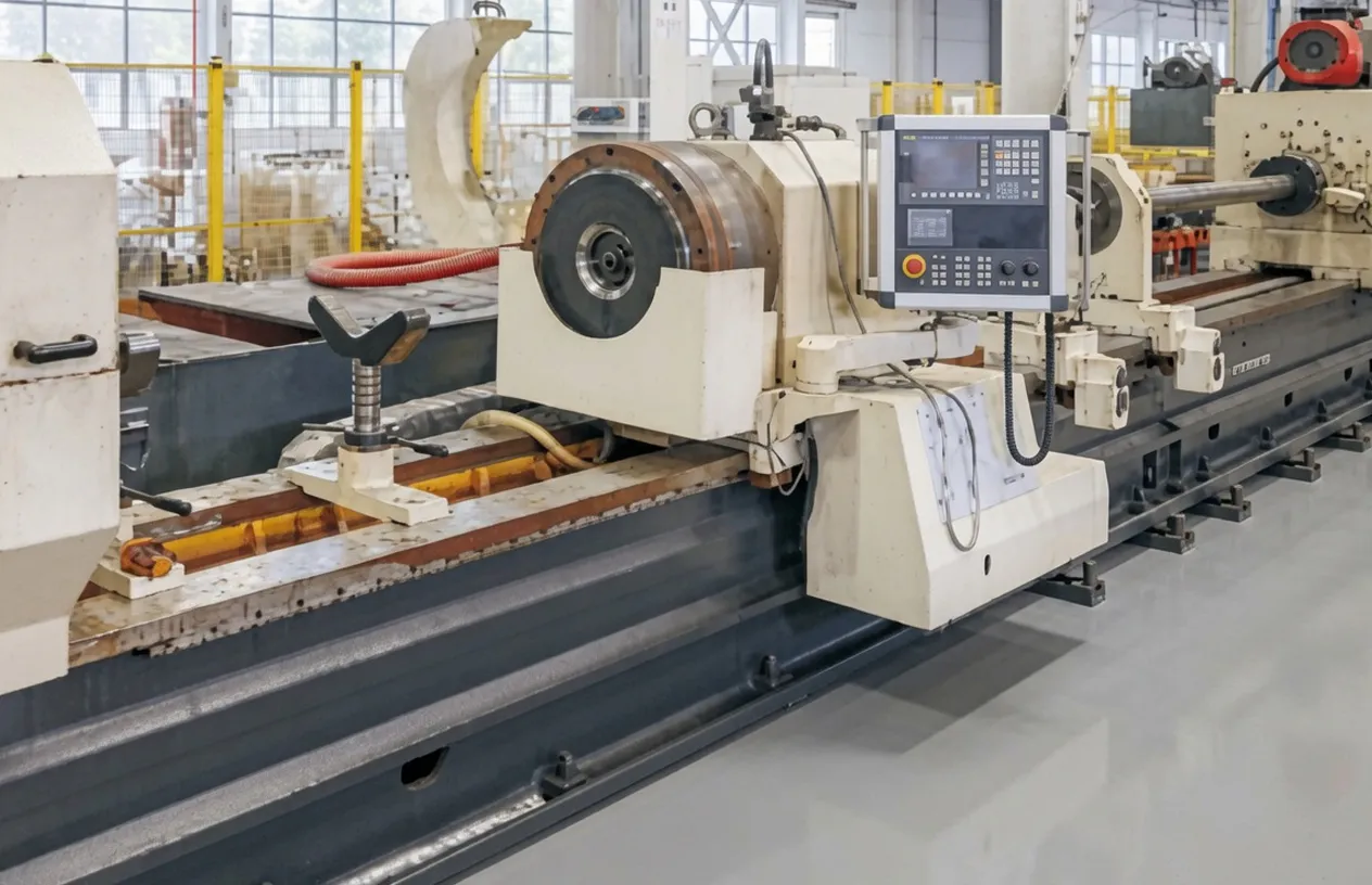
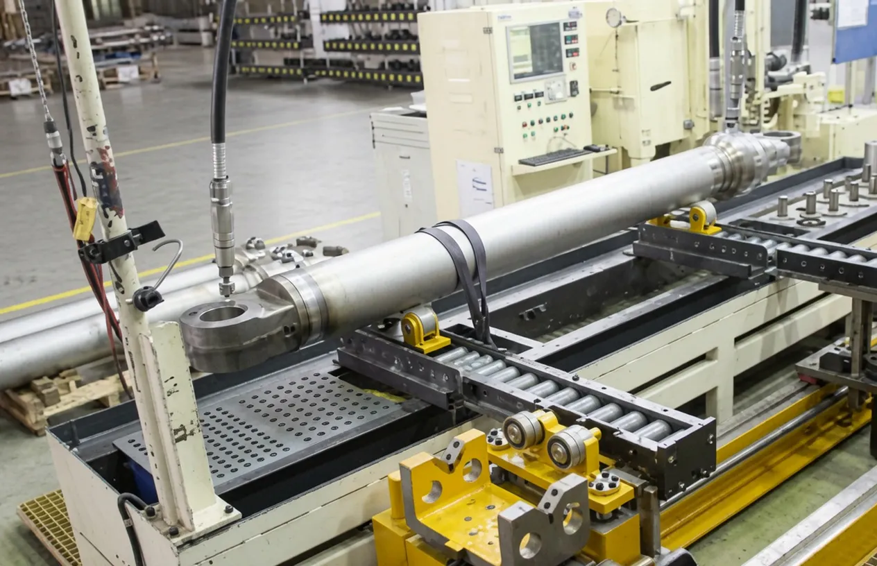
Our manufacturing facility operates large-format CNC deep-hole boring and honing machines capable of processing Φ280 mm bore lifting hydraulic cylinder units to precise dimensional standards, high-capacity hard chrome rod plating lines for Φ160 mm and larger rods, and hydraulic pressure test benches rated to 50 MPa for 100% production testing of heavy crane cylinders at proof pressure before dispatch. Technical documentation for French and EU crane regulatory compliance — including EN 13000 hydraulic system test certificates, material certificates, dimensional drawings, and pressure test reports — is available for all lifting hydraulic cylinder models supplied for crane applications.
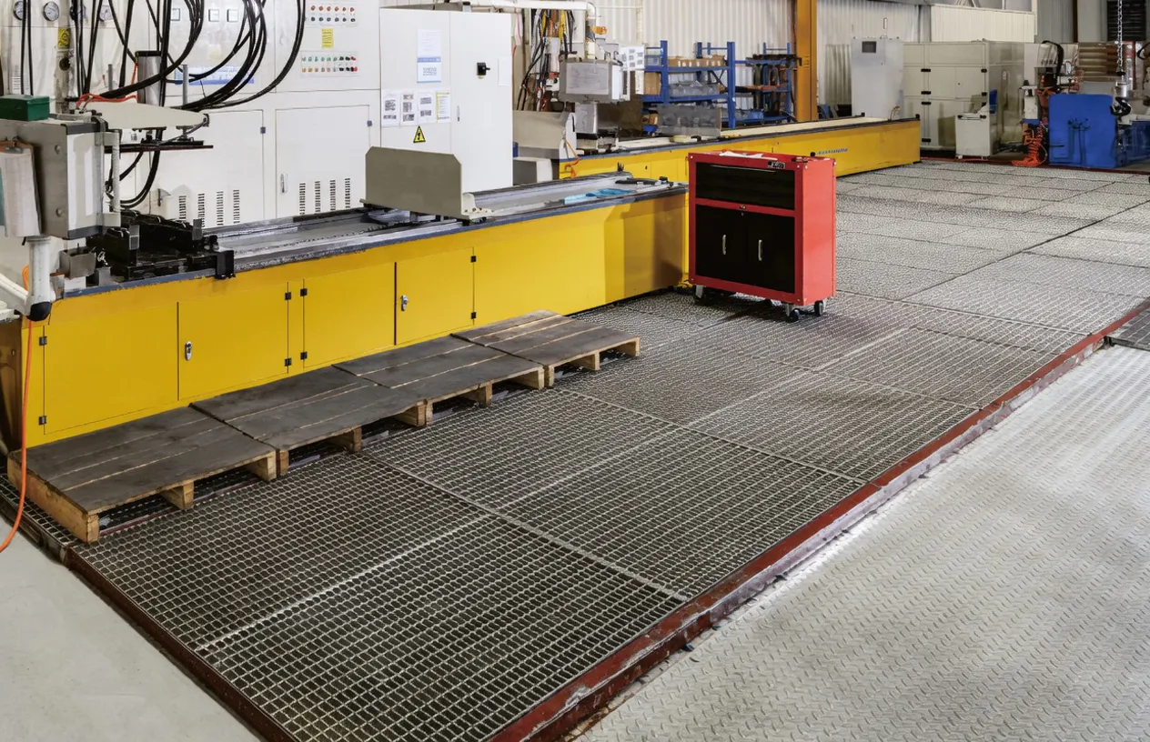
WorkShop
9. Compatible Products — Complete Crane Hydraulic System Supply
A crawler crane hydraulic system includes multiple cylinder circuits beyond the main luffing lifting hydraulic cylinder. We supply compatible hydraulic cylinder components for comprehensive crane cylinder procurement programs.
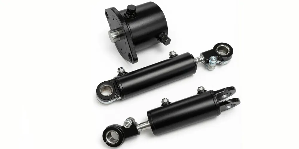
Tilt Cylinder Series
Crawler cranes incorporate multiple Tilt Cylinders in addition to the main luffing lifting hydraulic cylinder — for lattice boom angle adjustment auxiliary circuits, jib positioning, and counterweight deployment mechanisms. Our tilt cylinder range covers the bore sizes and pressure ratings used in these crane auxiliary circuits, providing a single-source supply option for French crane manufacturers and service organizations who need consistent documentation standards across all hydraulic cylinder types in the crane technical file for EN 13000 and Arrete du 1er mars 2004 compliance.
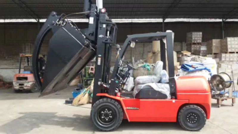
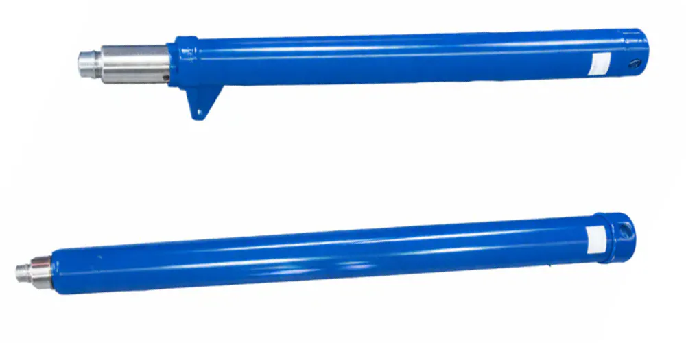
กระบอกยกของรถยก
Heavy lifting contractors and crane rental companies in France operating crawler cranes also maintain fleets of forklifts and material handling equipment at their crane yards, workshops, and project sites. Our Forklift Lift Cylinder range covers the complete specification for counterbalanced forklifts, reach trucks, and heavy telehandlers in bore sizes from Φ50 through Φ120 mm. Consolidating crane luffing lifting hydraulic cylinder and forklift cylinder procurement with a single manufacturer reduces supplier qualification effort and ensures consistent documentation standards for French lifting equipment regulatory compliance across the complete equipment fleet.
Hydraulic Pump Station
The hydraulic pump station powering the crawler crane luffing and slewing circuits must deliver sustained high flow at the 31.5 MPa working pressure required by this lifting hydraulic cylinder. We supply high-pressure hydraulic power units with variable-displacement piston pumps, pressure-compensated flow control, and cooling systems rated for continuous heavy-duty crane hydraulic operation. Specifying the pump station alongside the lifting hydraulic cylinder allows verification of flow rate compatibility with the cylinder bore area — a critical parameter that determines whether the boom luffing speed meets the crane performance specification required by French lifting contractors for their planned project programs.
Frequently Asked Questions
Q1. What is a crawler crane lifting hydraulic cylinder and how does it control the boom angle during heavy lifts on French construction sites?
A crawler crane lifting hydraulic cylinder controls the main boom luffing angle — the angle of the boom from horizontal — by extending or retracting in response to hydraulic oil pressure from the crane hydraulic circuit. When extended, the lifting hydraulic cylinder pushes the boom upward through its moment arm on the boom structure above the boom foot pivot; when retracted, it allows the boom to lower in a controlled manner under gravity, metered by the counterbalance valve. On French construction and industrial sites, this lifting hydraulic cylinder is the primary means of positioning the boom tip for the lift path required to place a load at a specific working radius and height, making its precision, reliability, and fail-safe function central to crane safety and lift plan execution.
Q2. How to calculate the lifting capacity of a hydraulic cylinder in a crawler crane application, and what force does the EP-Φ280×Φ160×2200 provide?
The hydraulic force available from a lifting hydraulic cylinder is calculated as F = A × P, where A is the bore area in mm² and P is the working pressure in MPa, giving the force in Newtons (divide by 1,000 for kN). For the EP-Φ280×Φ160×2200 lifting hydraulic cylinder on extension: bore area = π × 140² = 61,575 mm²; force = 61,575 × 31.5 = 1,939,613 N = 1,940 kN (approximately 197.7 tonnes-force). To translate this into crane boom lifting capacity, the hydraulic force is multiplied by the cylinder moment arm on the boom to give the available luffing moment, which is then divided by the combined moment arm of the boom self-weight and suspended load at the working radius to obtain the permitted load. This calculation requires the specific crane geometry and must be performed by the crane manufacturer or a structural engineer for each specific crane model.
Q3. Where can I find a reliable lifting hydraulic cylinder manufacturer in France or Europe supplying crane-grade cylinders with EN 13000 compliance documentation?
As a specialist lifting hydraulic cylinder manufacturer, we supply crawler crane lifting hydraulic cylinders including the EP-Φ280×Φ160×2200 to French crane manufacturers, crane rental companies, and heavy lift contractors with CIF French port delivery terms and EN 13000-compatible compliance documentation including pressure test certificates, material certificates, and dimensional drawings. Contact our export engineering team with your lifting hydraulic cylinder specification, quantity, and required delivery schedule for a quotation and technical confirmation. For urgent crane overhaul requirements, we maintain a priority manufacturing schedule for replacement crane lifting hydraulic cylinder orders that require accelerated lead time.
Q4. What working pressure does the EP-Φ280×Φ160×2200 lifting hydraulic cylinder operate at, and is it compatible with standard European crawler crane hydraulic systems?
The EP-Φ280×Φ160×2200 lifting hydraulic cylinder is rated at 31.5 MPa working pressure (315 bar), which is the standard operating pressure for the luffing circuits of crawler cranes in the 100 to 500-tonne capacity class used across European construction markets. The 40 MPa maximum withstand pressure satisfies the EN 13000 proof pressure requirement for crane hydraulic cylinders. The lifting hydraulic cylinder port dimensions and hydraulic connection specifications must be verified against the crane hydraulic circuit design for each specific application, as port sizes and fitting specifications vary between crane manufacturers even within the same working pressure class.
Q5. What is the service life of a crawler crane lifting hydraulic cylinder and when should it be replaced at French nuclear maintenance sites?
Crawler crane lifting hydraulic cylinders are designed for a service life of 10 to 20 years, typically corresponding to 10,000 to 30,000 luffing cycles depending on the cycle rate of the specific crane application. At French nuclear plant maintenance sites, where crane utilization during outage windows is intensive, a lifting hydraulic cylinder may accumulate its design life cycle count in 8 to 12 years of outage support operation. Replacement is triggered by rod seal leakage that cannot be corrected by seal kit renewal, rod surface damage beyond the polishing or replating threshold, bore wear exceeding dimensional tolerance, or a defined lifecycle-based replacement interval established in the crane maintenance plan under the nuclear facility quality assurance program (QAP) requirements for lifting equipment at French nuclear sites.
Q6. Which hydraulic oil is recommended for the crawler crane lifting hydraulic cylinder circuit operating at 31.5 MPa in French outdoor environments?
For crawler crane lifting hydraulic cylinder circuits operating at 31.5 MPa in French outdoor environments, ISO VG 46 anti-wear mineral hydraulic oil with zinc-dialkyl-dithiophosphate (ZDDP) additives is the standard recommendation for operating temperatures of 5°C to 60°C. For crane operation in northern France during winter months where cold start temperatures below 0°C are expected — for example at offshore wind port assembly sites in Dunkerque or nuclear plant sites in Normandy during winter outages — ISO VG 32 low-temperature mineral oil or a multigrade VG 32/46 provides adequate viscosity at cold start without excessive viscosity at normal operating temperature. The seal materials in the EP-Φ280×Φ160×2200 lifting hydraulic cylinder are compatible with both mineral oil grades across the outdoor operating temperature range of -20°C to +80°C.
Q7. What are the EN 13000 inspection requirements for a crawler crane lifting hydraulic cylinder at the mandatory periodic inspection in France?
Under EN 13000 and the French Arrete du 1er mars 2004 periodic inspection protocol, the crawler crane lifting hydraulic cylinder inspection includes: visual inspection of the rod chrome surface for corrosion, scratches, and dents; check of rod seal condition by observing oil trace presence on the rod behind the wiper seal; verification of lifting hydraulic cylinder mounting pin and bracket condition; hydraulic pressure hold test at working pressure with measurement of any rod drift indicating internal seal bypass; and measurement of counterbalance valve response to verify that the anti-runaway function is operational. The inspection body issues a written inspection report confirming lifting hydraulic cylinder condition, which is filed in the crane inspection dossier required to maintain the French operating permit validity under lifting equipment regulations.
Q8. What are the key differences between the lifting hydraulic cylinder types available for crawler cranes and how do I select the correct specification for a French heavy lift project?
Lifting hydraulic cylinder types for crawler cranes differ in bore diameter (determining force output), stroke length (determining boom angle range), rod diameter (determining pull force and buckling resistance), working pressure (reflecting the crane hydraulic circuit pressure class), and mounting configuration (pin, trunnion, or flange). For a French heavy lift project, lifting hydraulic cylinder selection starts with the crane manufacturer design specification that matches the required lift capacity and working radius to a specific crane model — the luffing cylinder for that model is then the required specification. For replacement procurement, the existing lifting hydraulic cylinder physical measurements and the crane technical documentation provide the specification. Our engineering team can assist French procurement teams in cross-referencing existing cylinder model numbers to our manufactured specifications for replacement supply programs.
Q9. When should a crawler crane lifting hydraulic cylinder seal kit be renewed versus full cylinder replacement during a French crane overhaul?
Seal kit renewal is appropriate when the rod chrome surface is in acceptable condition (no scratches deeper than 0.05 mm, no rust pitting, no chrome delamination), the barrel bore is within dimensional tolerance (ovality less than 0.05 mm), and the mounting hardware is structurally sound. Full lifting hydraulic cylinder replacement becomes necessary when the rod chrome is beyond polishing or local repair — typically when surface damage extends over more than 5% of the sealed rod length — when the barrel bore shows significant wear or scoring from contaminated hydraulic oil, or when the lifting hydraulic cylinder has sustained a structural overload event (detected by permanent rod bend or housing crack). For French crane operators maintaining crane inspection records under the Arrete du 1er mars 2004, the decision between seal kit renewal and full lifting hydraulic cylinder replacement should be documented in the crane maintenance record with the inspection body endorsement confirming continued crane fitness for service.
Source the EP-Φ280×Φ160×2200 Crawler Crane Lifting Hydraulic Cylinder
Contact our export team for technical specifications, EN 13000 compliance documentation, and CIF French port delivery quotations for crawler crane manufacturers, rental companies, and heavy lift contractors across France and the EU.
Editor: PXY