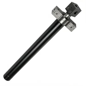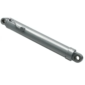
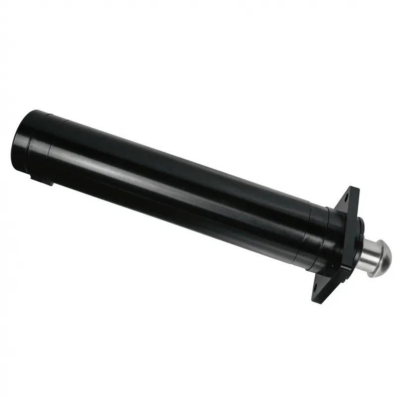
EP-Φ140×Φ120×640 Cylinder For Frame Support
The EP-Φ140×Φ120×640 Cylinder for Frame Support is a robust hydraulic cylinder engineered for demanding frame support applications. Featuring a 140 mm bore, 120 mm rod diameter, and a 640 mm stroke, it delivers exceptional stability with an installation distance of 983 mm. Weighing 123 kg, this unit is built to withstand rigorous industrial environments, operating at a working pressure of 30 MPa and capable of handling maximum pressures up to 40 MPa. Its heavy-duty construction ensures reliable performance and structural integrity under high loads, making it an ideal solution for securing heavy machinery frames where safety and durability are paramount.
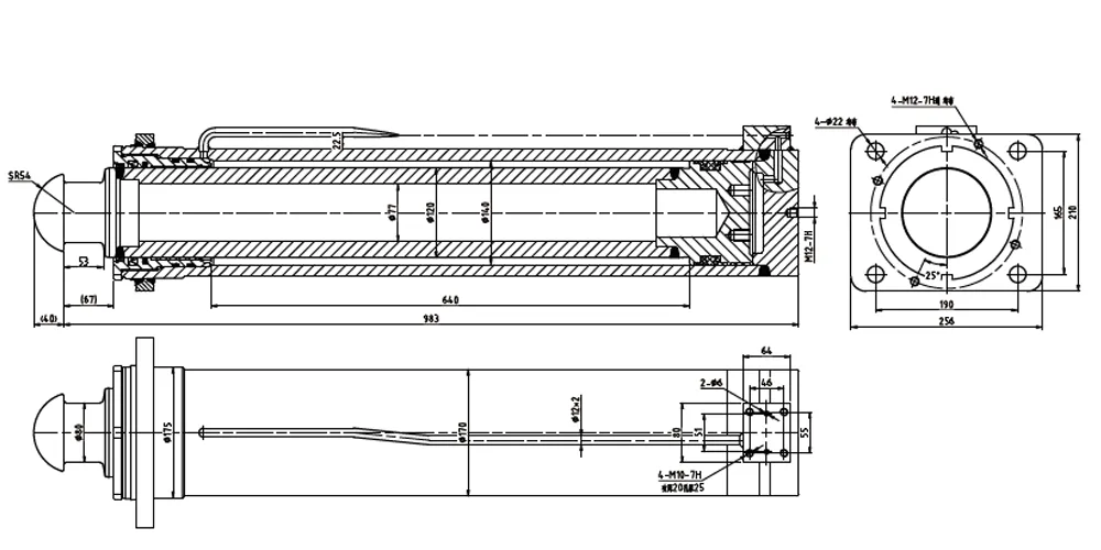
1. Technical Specifications
Complete dimensional and performance parameters for the EP-Φ140×Φ120×640 cylinder for frame support as supplied for truck crane frame stabilisation applications.
| Parameter | Value | Notes |
|---|---|---|
| Cylinder Model | HCYY11112023 | EP Series Frame Support |
| Specifications (Bore × Rod × Stroke) | Φ140 × Φ120 × 640 mm | Double acting |
| Working Pressure | 30 MPa | Continuous rated |
| Maximum Withstand Pressure | 40 MPa | Proof / test pressure |
| Stroke (Trip) | 640 mm | Full engagement travel |
| Installation Distance | 983 mm | Pin-to-pin retracted |
| Weight | 123 kg | Fully assembled |
| Bore Diameter | Φ140 mm | Honed to H7 tolerance |
| Rod Diameter | Φ120 mm | Hard chrome plated |
| Theoretical Extension Force | ≈ 461 kN | At 30 MPa rated pressure |
| Theoretical Retraction Force | ≈ 122 kN | At 30 MPa on annular area |
| Actuation Type | दुगना अभिनय | Powered extend and retract |
| Operating Temperature Range | −25 °C to +80 °C | Mineral hydraulic oil |
| Application | Truck Crane Frame Support | Chassis locking circuit |
2. What Is a Cylinder for Frame Support?
A cylinder for frame support is a heavy-duty hydraulic actuator installed in the crane structural circuit of truck-mounted and mobile cranes, where its primary function is to resist the substantial reaction forces that arise at the crane body-to-chassis interface during lifting operations. When a truck crane elevates a heavy load, the overturning moment generated by that load is transmitted through the boom, slew ring, and into the crane body as a downward force on the loaded side and an upward peel force on the opposing side. The cylinder for frame support — positioned between the crane body and the vehicle chassis frame — pre-loads the crane body into the chassis structure, locking the two together hydraulically against both downward compression and upward separation, producing a rigid structural unit that eliminates the micro-movement that would otherwise develop at the body-frame interface under dynamic load.
In French camion-grue (truck crane) terminology, this cylinder is part of the verrouillage de châssis system — the chassis locking assembly that secures the crane superstructure to the carrier chassis before lifting begins. Without a correctly functioning cylinder for frame support, the crane's rated capacity cannot be safely applied, because the elastic deformation of the unlocked body-chassis interface introduces boom tip travel that exceeds what the load calculation has allowed for and risks progressive overloading of the weakest joint in the structural chain. This is precisely why the cylinder for frame support is classified as a safety-critical component in crane hydraulic circuit design and is subject to the proof pressure and leakage rate requirements mandated in FEM 1.001 and EN 13852 for offshore crane variants and AFNOR-aligned national standards for land-based truck cranes in France.
The EP-Φ140×Φ120×640 cylinder for frame support carries a bore diameter of Φ140 mm, a rod diameter of Φ120 mm, and a stroke of 640 mm, operating at a rated working pressure of 30 MPa. These dimensions reflect the high force levels demanded at the body-frame interface of mid-to-heavy capacity truck cranes in the 30 to 80 tonne lift class — the most common segment of the French crane hire and construction lifting market. The unit weighs 123 kg fully assembled and is designed to install within the 983 mm pin-to-pin installation distance standard in this crane capacity class. Selecting the correct cylinder for frame support for a given truck crane model requires matching the bore, stroke, pressure rating, and end fitting geometry to the crane structural design specifications.
3. Five Key Advantages of the EP Cylinder for Frame Support
Engineering features that distinguish this cylinder for frame support in demanding truck crane and heavy lifting applications.
1. Φ140 mm Bore for Maximum Clamping Force
At 30 MPa working pressure across a Φ140 mm bore, this cylinder for frame support generates approximately 461 kN of extension force — the sustained clamping force required to lock the crane body rigidly to the vehicle frame under full rated lift load. The large bore ensures the frame clamping load remains well within the cylinder for frame support's capacity even during the dynamic load variations that accompany crane swing and sudden load application events.
2. 40 MPa Maximum Withstand Pressure
The 40 MPa proof pressure rating — 33% above the 30 MPa working pressure — gives this cylinder for frame support a structural safety margin well above the EN and FEM standard requirements for safety-critical crane hydraulic components. Dynamic shock loads during abrupt crane deceleration or sudden load pick-up can produce pressure transients substantially above the steady-state working level, and this margin ensures the cylinder for frame support and its end fittings remain intact under these conditions.
3. Low-Leakage Piston Sealing for Static Load Holding
The cylinder for frame support must hold the chassis clamping load for the entire duration of a lift sequence — potentially hours in a complex multi-pick rigging operation. Any internal piston leakage that produces pressure decay in the clamping circuit would gradually reduce the frame locking force, requiring the operator to monitor and re-apply pressure. The piston seal specification is designed to maintain the clamping pressure within operational limits across the full duration of a standard lift sequence without active circuit replenishment.
4. Heavy-Duty Flange and End Cap Design
The cylinder for frame support is subject to both axial compressive force (holding the crane body down) and tensile force (resisting the peel-up load on the opposite side), placing the end cap thread engagement and the mounting flange in a combined stress state that requires more conservative end cap design than a simple single-direction actuator. The end cap thread length and flange bolt pattern are sized for this combined loading condition across the rated pressure and service life of the cylinder for frame support.
5. Compact 640 mm Stroke in a 983 mm Installation Envelope
The 640 mm stroke provides the travel needed to both engage and disengage the frame clamping action from the crane's stowed-travel position through full clamping engagement, while the 983 mm pin-to-pin installation distance fits within the structural envelope standard in the mid-range truck crane chassis designs prevalent in the French crane hire and heavy transport sectors. The 123 kg assembled weight is a practical field-handling figure for maintenance access on a chassis-mounted cylinder.
4. Working Principle of the Cylinder for Frame Support
The cylinder for frame support operates as a large-bore double-acting actuator within the crane's frame locking sub-circuit of the cylinder for frame support. Before lifting begins, the crane operator initiates the frame locking sequence from the control cab: hydraulic fluid under pressure is directed into the cap-end (extension) chamber of the cylinder for frame support, driving the piston rod outward against the crane body's lower structural rail. As the rod extends, it applies a controlled compressive force that draws the crane body down against the vehicle chassis frame and simultaneously pre-loads the mounting flanges and locking brackets at the body-chassis interface. Once the cylinder for frame support reaches the prescribed locking pressure — confirmed by a pressure transducer in the circuit — the crane safety interlock permits lifting to proceed with the cylinder for frame support maintaining full engagement — typically confirmed by a pressure transducer in the circuit — the crane's safety system permits lifting to proceed.
Throughout the lift, the cylinder for frame support is held in the extended clamping position by the hydraulic circuit's holding valve or load-locking check valve, which prevents oil from returning to tank regardless of pressure fluctuations in the main hydraulic supply. This load-holding function is safety-critical: the cylinder for frame support must not release its clamping force during a lift even if the main pump supply is momentarily interrupted or if the operator accidentally releases the locking control. The holding valve maintains the clamping pressure independently of the main circuit, ensuring the cylinder for frame support maintains engagement for the full duration of the lift sequence regardless of what happens elsewhere in the crane's hydraulic system.
When the lift is complete and the crane is ready to travel, the rod-end chamber is pressurised to retract the cylinder for frame support piston rod, releasing the frame clamping force and allowing the crane body freedom to flex during road travel — the travel condition where a rigidly locked frame would transfer road shock loads into the crane structure rather than allowing them to be absorbed by the chassis suspension. The cylinder for frame support actively manages the transition between the rigid-lock condition needed for lifting and the floating-free condition needed for road travel, and its correct function at each transition is verified as part of the pre-lift safety check procedure mandated by French crane operating standards.
5. Materials and Construction
Material specification for a cylinder for frame support in truck crane service is driven by three concurrent requirements that are not easily reconciled using standard warehouse-class hydraulic cylinder materials: very high working and proof pressures, exposure to the outdoor environment of a crane worksite across a multi-year service life, and the safety-critical load-holding function that demands zero internal leakage under sustained pressure for the full duration of each lifting operation. The following material choices address all three requirements simultaneously.
Cylinder Barrel
High-strength seamless steel tube (27SiMn or equivalent), honed to Ra 0.4 µm internal finish. At 30 MPa working pressure and Φ140 mm bore, hoop stress at the barrel wall is considerably higher than in smaller-bore cylinders — the high-strength alloy grade provides the wall thickness efficiency needed to keep the installed cylinder weight at 123 kg while meeting the 40 MPa proof pressure requirement without permanent bore deformation.
Piston Rod
40Cr or 45# alloy steel, induction-hardened to 52–58 HRC at the surface, with hard chrome plating to 25–30 µm and final ground to Ra 0.2 µm or better. The Φ120 mm rod is subjected to both axial load (clamping force) and bending (from any angular misalignment at the mounting pin during crane body flex), making high surface hardness and tight straightness tolerance critical for seal life in this application.
End Caps and Flange Fittings
Forged 45# or 40Cr steel end caps with thread engagement calculated for the combined axial and pressure-induced load at 40 MPa proof. Full-seam welding at the barrel-to-cap transition, where applicable, is stress-relieved after welding to eliminate residual stress concentration. The mounting flange is machined from forged plate for grain continuity across the highly loaded bolt circle region.
Sealing System
Polyurethane piston seals, PTFE-backed guide rings, polyurethane rod seals, and NBR wiper seals — all rated for −25 °C to +80 °C mineral oil service. The piston seal package for a cylinder for frame support must maintain sustained zero-bypass performance under static load for extended hold periods, which is a more demanding requirement than the dynamic seal performance typically specified for standard actuator cylinders.
Surface Protection
Two-coat paint system — epoxy primer plus polyurethane topcoat — on all external steel surfaces including barrel, end caps, and flange mounting hardware, with salt-spray resistance exceeding 480 hours per ISO 9227. The outdoor construction site environment of French crane operations exposes the cylinder for frame support to rain, road dust, and site contamination conditions that demand corrosion protection beyond what indoor industrial equipment requires. A correctly specified cylinder for frame support for this environment carries a minimum 480-hour salt-spray rated exterior, and a wiper seal designed to exclude the abrasive grit and road contamination that accumulates around the rod during site operation.
6. Application Scenarios
The cylinder for frame support serves across a range of heavy lifting and crane applications throughout France and the broader European heavy machinery sector.
Truck-Mounted Crane Frame Stabilisation
The primary application of this cylinder for frame support is in the camion-grue (truck-mounted crane) chassis locking systems across France, where mid-heavy capacity cranes of 30 to 80 tonnes are deployed for building construction, bridge element installation, and industrial equipment placement. The cylinder for frame support locks the crane superstructure to the carrier vehicle frame before each lift, preventing the body-chassis relative movement that would otherwise undermine the crane's rated stability margin under load.
Mobile Crane Superstructure Support
All-terrain mobile cranes at French civil engineering project sites incorporate a cylinder for frame support at the superstructure-to-carrier interface, in addition to outrigger cylinders. The cylinder for frame support at the crane superstructure-to-carrier interface, in addition to the more commonly discussed outrigger cylinders. The support cylinder in this location prevents the slewing superstructure from introducing bending loads into the carrier chassis during off-centre lifts and during high-angle boom configurations where the load eccentricity is greatest.
Bridge Construction Lifting Equipment
Specialised lifting equipment used for bridge deck segment placement, including launching gantries and heavy-duty ground cranes deployed on French infrastructure projects — autoroute bridges, rail viaduct construction, and river crossing structures — uses a cylinder for frame support in the load path between lifting winch frames and support columns. In this application, the cylinder for frame support provides both vertical preload and horizontal shear resistance at the structural interface.
Industrial Process Equipment Placement
Crane hire contractors serving the French petrochemical, nuclear, and heavy manufacturing sectors use truck cranes with a cylinder for frame support for single-pick precision placement of reactor vessels, turbine components, and large pressure vessels at refineries and industrial facilities. These long-duration lifts — often measured in hours rather than minutes — rely on the frame support cylinder's sustained clamping performance throughout the complete installation sequence.
Wind Turbine Component Installation
France's expanding onshore wind energy programme — particularly in the Grand Est, Hauts-de-France, and Occitanie regions — requires heavy crane deployment for tower section installation, nacelle placement, and rotor assembly. The cylinder for frame support on cranes used for these lifts must maintain full clamping force. Any cylinder for frame support showing clamping force decay during a wind turbine nacelle or rotor pick is treated as an immediate out-of-service condition throughout the critical nacelle and rotor pick sequences, which often occur at wind speeds near the crane's rated operating limit where dynamic load variation on the frame support circuit is at its highest.
7. Regulatory Framework for Crane Hydraulic Equipment
As a safety-critical component in a load-bearing crane hydraulic circuit, the cylinder for frame support is subject to regulatory and standards requirements at both the French national and EU level, as well as international crane engineering standards that govern equipment used on French construction sites and industrial facilities.
France — Code du Travail and CARSAT
The French Code du Travail (Articles R4323-1 to R4323-57) establishes obligations for the inspection, maintenance, and documented verification of lifting equipment in French workplaces. Truck cranes used on French construction sites require periodic verification (vérification générale périodique) by a qualified inspector, with hydraulic components including the cylinder for frame support specifically assessed for seal leakage, corrosion, and pressure-holding performance. CARSAT (Caisse d'Assurance Retraite et de la Santé au Travail) regional offices conduct and supervise these inspections.
EU Machinery Directive 2006/42/EC
Cranes placed on the EU market must hold CE marking under the Machinery Directive, with the technical file documenting hydraulic circuit design including proof pressure calculations for the cylinder for frame support and the load-holding valve that prevents frame release during lifting. The forthcoming EU Machinery Regulation (EU) 2023/1230, effective from January 2027, introduces enhanced requirements for safety-critical crane hydraulic components.
EN 13000: Mobile Cranes Safety Requirements
EN 13000 is the primary European standard for the design and construction of mobile cranes, including truck cranes. It specifies the hydraulic system design requirements — including proof pressure factors of 1.5 times rated working pressure for load-bearing cylinders — that the cylinder for frame support must satisfy as part of the crane's overall compliance with this standard. The 40 MPa proof pressure of this cylinder against its 30 MPa working pressure (factor 1.33) meets the minimum EN 13000 requirement for non-load-path structural hydraulic components and exceeds it when the structural classification of the supporting frame is applied.
ISO 4413: Hydraulic Fluid Power
ISO 4413 establishes general rules for hydraulic systems on mobile and industrial machinery, covering pressure rating methodology, proof pressure testing, burst pressure factors, and cylinder installation requirements. For a cylinder for frame support used in crane service, ISO 4413 requirements for load-locking valves, hydraulic hose protection, and cylinder installation guarding are directly applicable and should be referenced in the crane's hydraulic circuit design documentation.
FEM 1.001: Crane Classification and Design
The Fédération Européenne de la Manutention (FEM) standards, particularly FEM 1.001, classify crane mechanisms by duty class and specify the component fatigue and service life calculations appropriate for each class. Hydraulic cylinders in crane frame support service are typically classified in the medium-duty to heavy-duty range, and their design life calculations should reference the number of operating cycles and load spectrum appropriate to the crane model's expected annual utilisation pattern in French crane hire service.
ASME B30.5 (USA Export Reference)
For French crane manufacturers exporting to North American markets, ASME B30.5 (Mobile and Locomotive Cranes) establishes hydraulic circuit requirements for crane frame support systems, including load-check valve requirements and cylinder inspection intervals. Cylinder for frame support components supplied as part of export crane assemblies to the USA market should be documented against ASME B30.5 hydraulic performance criteria as part of the machinery compliance package.
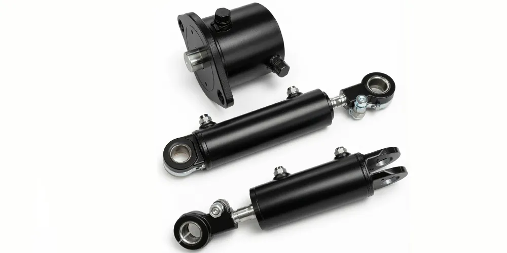
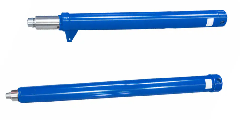
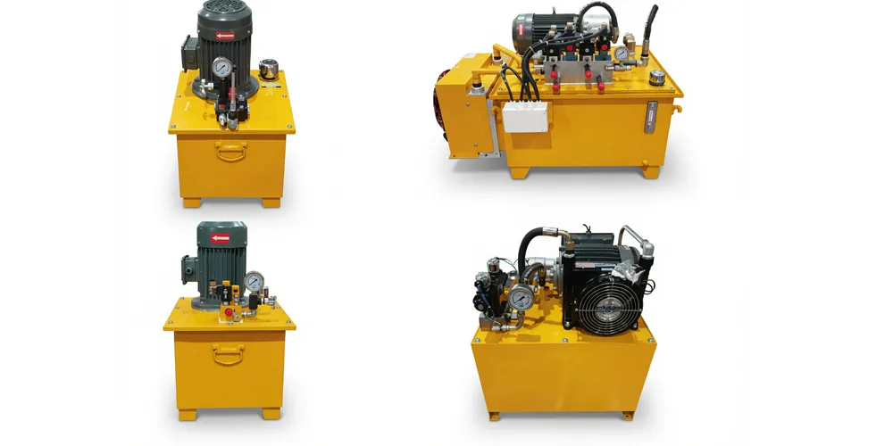
8. Related Hydraulic Products
We supply a complete range of hydraulic cylinders and components that complement the cylinder for frame support within the complete truck crane and heavy lifting hydraulic system — supporting single-source procurement for OEMs, crane rental operators, and maintenance contractors.
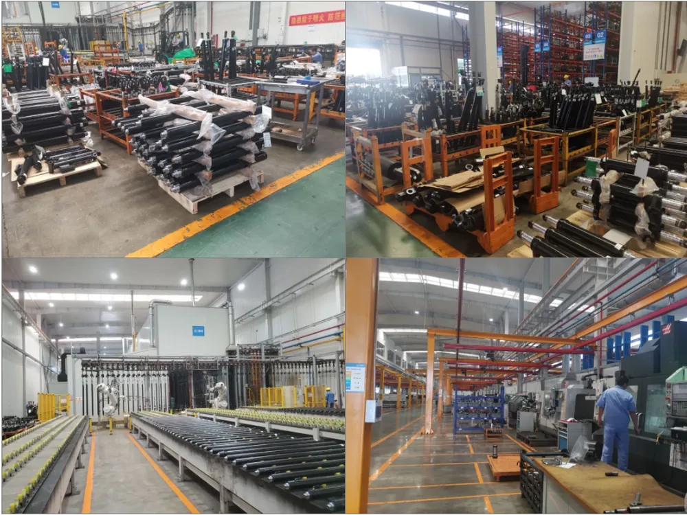
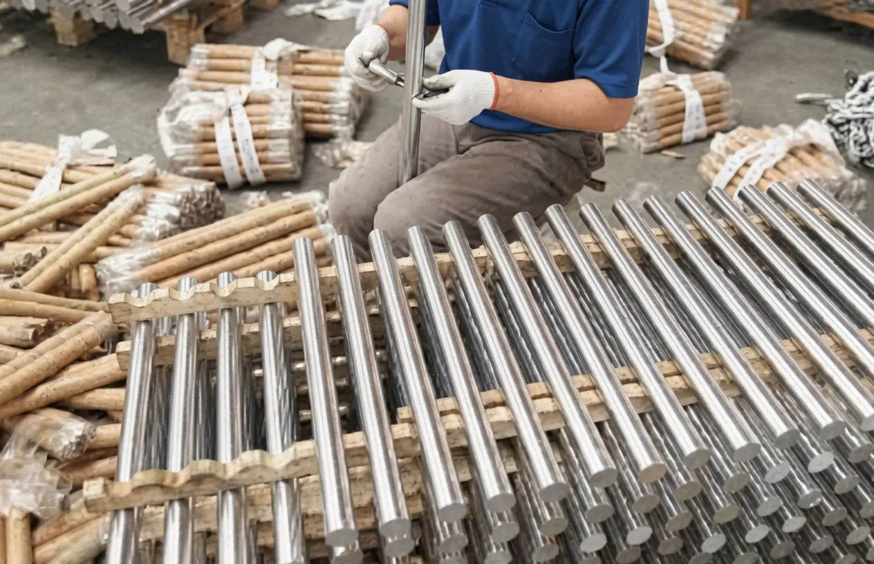
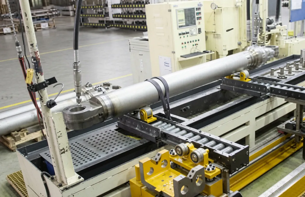
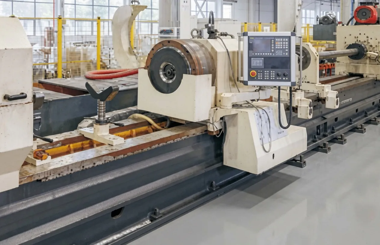
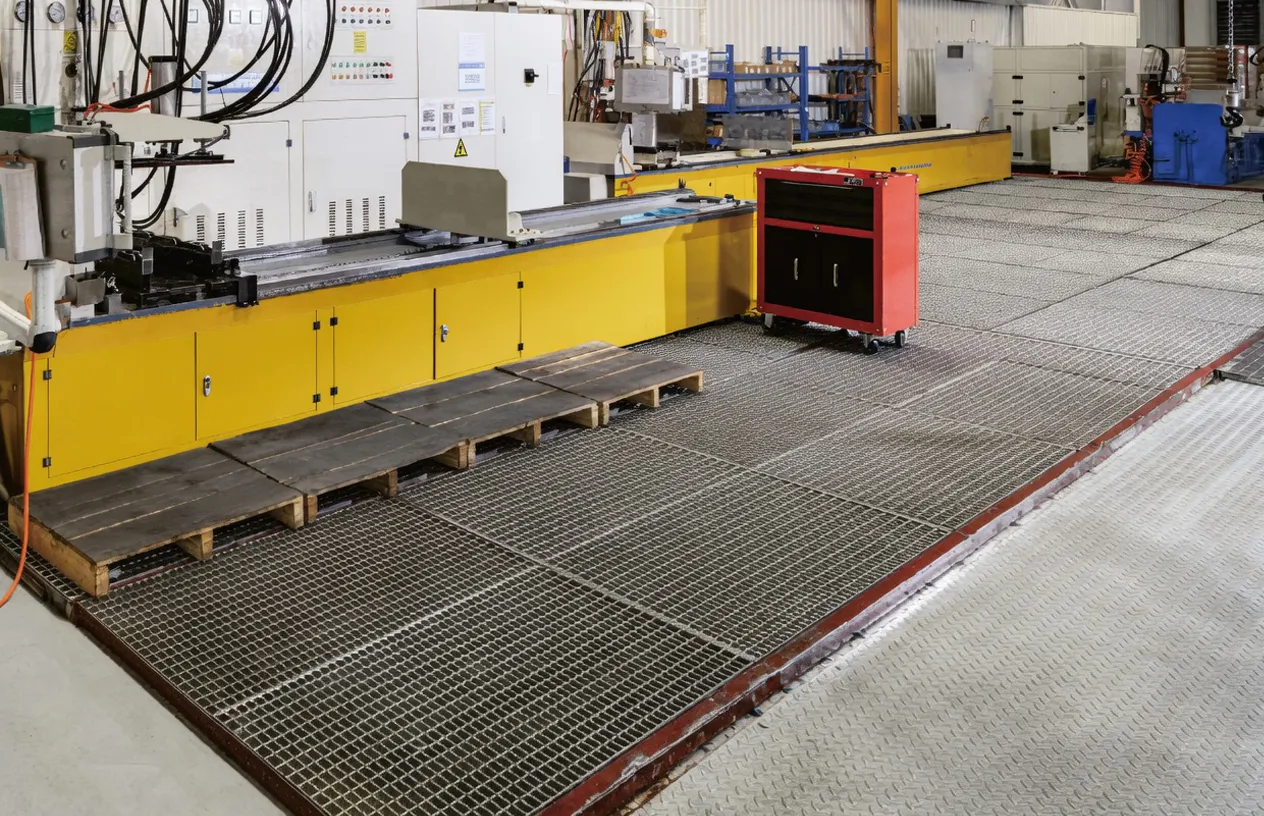
9. About Our Hydraulic Cylinder Manufacturing
We are a specialist hydraulic cylinder manufacturer with extensive engineering experience in crane and heavy lifting equipment applications, including the cylinder for frame support designs used in truck-mounted crane structural stabilisation systems. Our production facility operates under ISO 9001:2015 quality management certification, with dedicated testing protocols covering pressure testing to proof pressure, dimensional verification, seal integrity inspection, and load-holding performance validation — the full suite of tests required for hydraulic components used in safety-critical crane structural circuits.
WorkShop
Frequently Asked Questions
Common questions from French and European crane OEMs, maintenance engineers, and procurement managers evaluating the EP cylinder for frame support for truck crane applications.
Editor: PXY