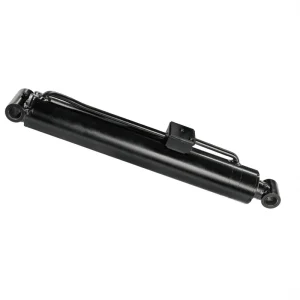
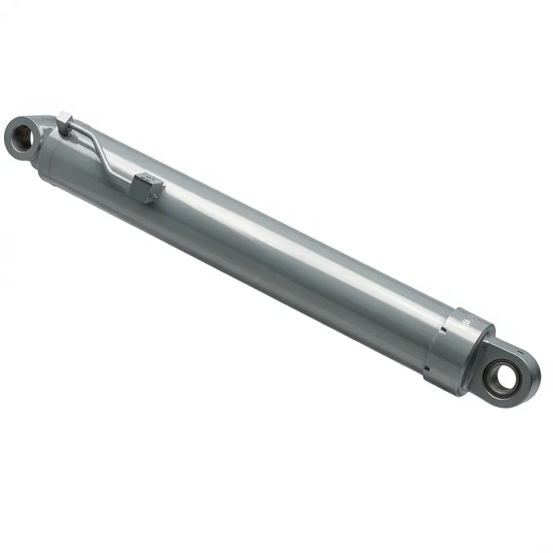
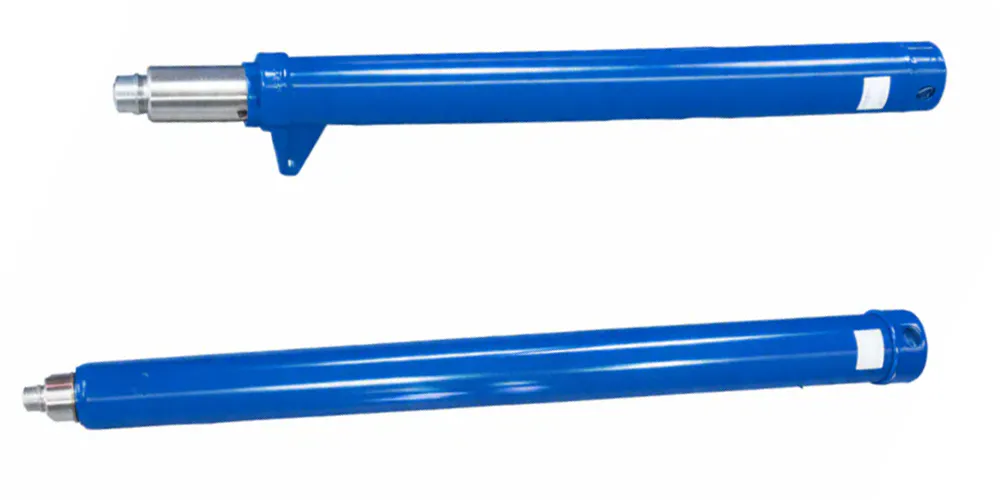
EP-Φ280×Φ250×3507 Main Boom Angle Cylinder
The EP-Φ280×Φ250×3507 Main Boom Angle Cylinder is a heavy-duty hydraulic cylinder engineered for precise main boom angle control in large-scale mobile cranes. With a 280 mm bore, 250 mm rod diameter, and a 3507 mm stroke, it delivers exceptional force and stability under extreme loads. Operating at a working pressure of 31.5 MPa and capable of withstanding up to 39 MPa, this cylinder ensures reliable performance in demanding lifting operations. Weighing 1155 kg and featuring an installation distance of 4218 mm, it is designed for seamless integration into high-capacity crane systems where structural integrity and operational safety are critical. Its robust construction supports continuous duty cycles in industrial and construction environments.
Truck Crane Hydraulic Cylinder Series
EP-Φ280×Φ250×3507 Main Boom Angle Cylinder
A precision-engineered main boom angle cylinder designed for truck crane luffing systems — delivering controlled angular positioning of the main boom under high-pressure hydraulic actuation with outstanding structural integrity and long service life.
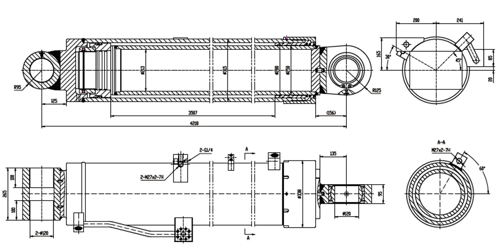
1. Technical Specifications — HCYY11112021 Main Boom Angle Cylinder (EP-Φ280×Φ250×3507 Main Boom Angle Cylinder)
All dimensional values are in millimetres unless stated otherwise. Force calculations represent theoretical values at rated working pressure without efficiency correction. Specifications conform to ISO 10100 pressure test acceptance criteria.
| Parameter | Value | Notes |
|---|---|---|
| Cylinder Model | HCYY11112021 | Truck crane main boom luffing series |
| Specifications (Bore × Rod × Stroke) | Φ280 × Φ250 × 3507 mm | Large-bore long-stroke configuration |
| Working Pressure | 31.5 MPa | Rated operating pressure of hydraulic system |
| Maximum Withstand Pressure | 39 MPa | Proof pressure; 123.8% of working pressure |
| Trip (Stroke) | 3507 mm | Full travel from minimum to maximum boom elevation |
| Installation Distance | 4218 mm | Pin centre to pin centre at fully retracted position |
| Weight | 1155 kg | Mechanical handling required; crane or lift equipment for installation |
| Bore Diameter | Φ280 mm (H8 tolerance) | Honed bore; Ra ≤ 0.4 µm; seamless steel tube |
| Piston Rod Diameter | Φ250 mm (h6 tolerance) | Hard chrome plated; Ra ≤ 0.2 µm; 42CrMo4 steel |
| Extension Force (theoretical) | ≈ 1,940 kN at 31.5 MPa | Based on full bore area π/4 × 280² × 31.5 |
| Retraction Force (theoretical) | ≈ 186 kN at 31.5 MPa | Based on annular area π/4 × (280²−250²) × 31.5 |
| Cap End Attachment | Integrated clevis / pin mount | Connects to crane superstructure pin-mount bracket |
| Rod End Attachment | Heavy-duty forged clevis fork | Pin-mounted to boom foot lug; aligned to luffing axis |
| Seal Compound | NBR (standard) / FKM (option) | ISO VG 46/68 oil compatible; FKM for cold-climate operation |
| Operating Temperature | −20°C to +80°C | FKM seals recommended for sub-zero applications |
Note: All forces are theoretical at rated pressure; actual output depends on mechanical efficiency and system back-pressure. Dimensional tolerances per ISO 6020-1.
2. About Our Φ280×Φ250×3507 Main Boom Angle Cylinder
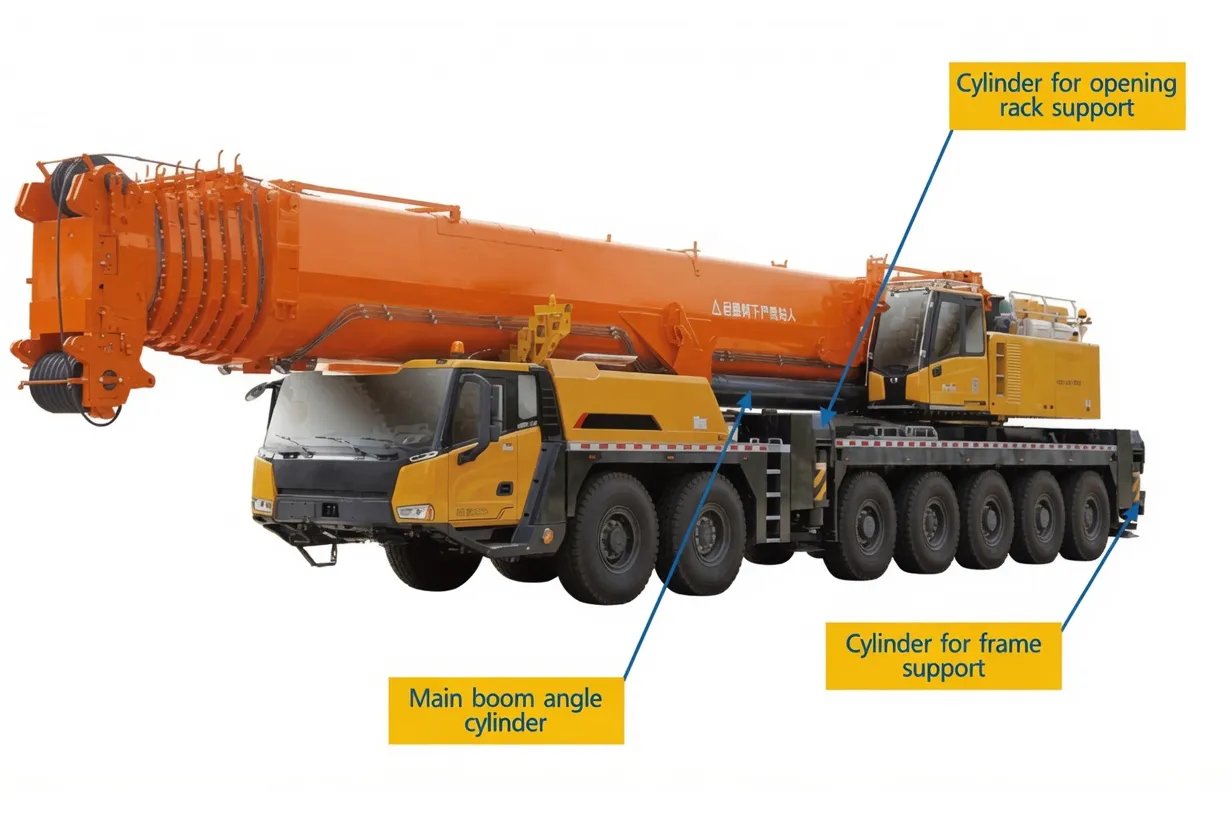
The EP-Φ280×Φ250×3507 is a high-capacity main boom angle cylinder engineered specifically for the luffing mechanism of truck-mounted cranes and other heavy lifting platforms. This main boom angle cylinder controls the elevation angle of the main boom — the primary structural arm from which the crane's lifting hook is suspended — by extending or retracting under the commands of the crane's hydraulic control system. The angular change achieved through the travel of this main boom angle cylinder directly governs the crane's working radius and maximum permissible lifted load at any given operating configuration, making the main boom angle cylinder one of the most safety-critical hydraulic actuators on the entire machine.
With a bore diameter of 280 mm, a piston rod diameter of 250 mm, and a stroke of 3507 mm, this main boom angle cylinder falls into the large-bore, long-stroke class that characterises truck crane luffing applications in the 100–400 tonne lifting capacity range. The exceptional rod-to-bore ratio of this main boom angle cylinder — with only 15 mm of annular clearance on each side between the rod and bore — reflects its primary function as a compressive structural member carrying the boom weight and lifted load reaction forces, rather than as a conventional force-generation actuator. Operating at 31.5 MPa working pressure with a maximum withstand pressure of 39 MPa, this main boom angle cylinder delivers a high extension force while maintaining the structural margins demanded by crane design standards across Europe, including France, Germany, and the United Kingdom.
This main boom angle cylinder — HCYY11112021 — is manufactured to the dimensional and performance specifications of the HCYY11112021 model and carries the complete technical documentation required for crane component qualification under European and international standards. The installation distance of 4218 mm and weight of 1155 kg in this main boom angle cylinder reflect the substantial structural scale of this main boom angle cylinder, which requires coordinated mechanical handling for installation and removal during crane maintenance or rebuild operations.
3. Working Principle of the Main Boom Angle Cylinder in Truck Crane Luffing
The main boom angle cylinder is a double-acting hydraulic cylinder that controls the angular elevation of the crane's main boom around its foot-pin pivot point. When pressurised hydraulic oil enters the cap-end port at up to 31.5 MPa working pressure, it acts on the full bore area of the main boom angle cylinder 280 mm barrel, generating an extension force of approximately 1,940 kN that pushes the piston rod outward. Since the rod end of this main boom angle cylinder is pinned to the boom structure and the cap end is pinned to the crane's superstructure frame, this extension causes the boom to rotate upward around its pivot, increasing the elevation angle and reducing the effective working radius. The reverse operation — directing oil into the rod-end port — retracts the cylinder and lowers the boom.
A key functional characteristic that sets this main boom angle cylinder apart that distinguishes it from standard actuator cylinders is its role as a structural load-bearing member during lifting operations. Once the boom elevation target is achieved, the hydraulic system holds the main boom angle cylinder at its extended length under a combination of load-holding valves and counterbalance valves. During the actual crane lift, the main boom angle cylinder is not merely a hydraulic device — this main boom angle cylinder is an active structural strut carrying compression and bending loads induced by the lifted weight, the boom's own mass, and wind loading on the exposed boom structure. The 250 mm rod diameter leaves only 15 mm of annular clearance on each side, producing a very high rod-to-bore ratio that is specifically engineered for this compressive structural role rather than for maximising retraction force.
The hydraulic system feeding this main boom angle cylinder circuit includes proportional control valves that allow smooth, variable-speed boom elevation at precise angular increments. Modern truck cranes in France and across Europe use load-sensing hydraulic circuits that automatically modulate pump output based on the main boom angle cylinder's instantaneous load demand, improving energy efficiency across the main boom angle cylinder luffing cycle. The counterbalance valve integrated into the luffing circuit prevents boom free-fall if a hydraulic hose fails during a lift — a safety-critical requirement under EN 13000 (Mobile Cranes) and directly relevant to the main boom angle cylinder as the primary load-bearing actuator in this circuit.
4. Manufacturing Structure of the Main Boom Angle Cylinder — Component by Component
Every structural element of this main boom angle cylinder design is engineered to address the combined demands of high hydraulic pressure containment and structural load-bearing under the extreme conditions of heavy crane operation. The following describes the principal structural components and their specifications.
Cylinder Barrel
Produced from seamless cold-drawn steel tube conforming to EN 10305-1, the 280 mm bore barrel wall is calculated to satisfy the 39 MPa proof pressure requirement while carrying the combined axial and bending loads of the structural role. After boring, the inner surface is precision-honed to Ra ≤ 0.4 µm, providing the consistent seal contact surface that prevents micro-scoring under the oscillatory loads transmitted from the boom during lifts. This is the foundation of what is the barrel of a hydraulic main boom angle cylinder in crane-grade applications — a precision pressure vessel and structural member simultaneously.
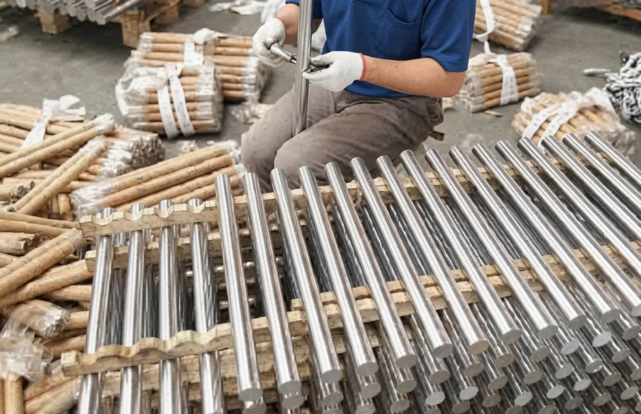
Piston Rod — 250 mm Diameter
The 250 mm piston rod is produced from 42CrMo4 alloy steel quench-and-tempered to a core tensile strength of minimum 1000 MPa. At 250 mm diameter, the rod of this main boom angle cylinder functions primarily as a compression strut. After precision machining to h6 tolerance, the rod receives hard chrome plating to a minimum 0.030 mm depth, ground and polished to Ra ≤ 0.2 µm. At 250 mm diameter, the chrome deposit volume is substantial — long-term chrome durability under the fretting and micro-movement loads of the structural hold mode is a critical quality parameter verified during production inspection at each unit's final release.
Piston Assembly
The piston carries the primary hydraulic seal and the guide ring that centres the rod within the bore. For this main boom angle cylinder, the piston guide ring contact area is generously proportioned is generous — wide enough to distribute the lateral bending load from the boom's own mass and external wind loading into the bore surface without metal-to-metal contact. The piston material is carbon steel, with the seating surfaces ground to the tolerances required for proper seal and guide ring function under the cylinder's full working pressure range.
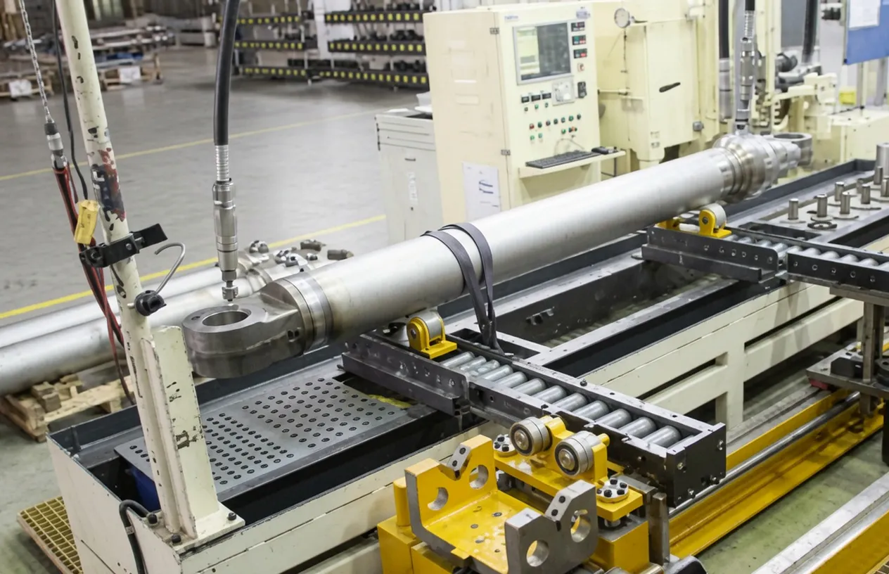
End Caps and Mounting Clevis
Both end caps are precision-machined from forged steel and are joined to the barrel by heavy-section thread or welded connections rated for the full proof pressure. The cap-end mounting clevis and rod-end clevis fork are forged steel components machined to precise pin bore diameters and face perpendicularity to ensure the main boom angle cylinder mounting axis aligns with the luffing geometry of the crane. Misalignment at the trunnion introduces bending into the rod that accelerates seal and guide ring wear — correct clevis geometry is a precision manufacturing requirement on crane-grade cylinders, not a secondary specification.
Gland / Rod Seal Housing
The gland assembly houses the wiper ring, primary rod seal, secondary seal, and guide ring in a machined housing that threads into the barrel cap-end bore. The wiper ring on the main boom angle cylinder rod entry is the primary defence against contamination ingress from crane site environments — including concrete dust at building projects, mineral grit at quarry and open-cast mining sites, and the salt-laden air at French port and coastal infrastructure projects. The wiper and primary seal are individually replaceable without full cylinder disassembly, simplifying planned maintenance during crane inspection intervals.
External Surface Protection
The external surfaces of the main boom angle cylinder barrel and non-chrome components receive a two-component epoxy-polyurethane coating over zinc phosphate primer, providing corrosion resistance appropriate for continuous outdoor crane deployment in France's varied climate zones — from the Atlantic coastal environments of Bretagne and the Loire estuary to the alpine construction sites of the Alpes and Pyrénées where temperature cycling and seasonal freeze-thaw accelerate conventional coating breakdown. The chrome-plated rod section is protected by a rod sleeve during transport and storage to prevent transit damage to the precision-ground surface.
5. Material System — Engineering for Crane-Grade Reliability
The material specification of this main boom angle cylinder must address two simultaneous and demanding requirements that are rarely combined in standard industrial hydraulic cylinders: the need to sustain 31.5 MPa hydraulic pressure in the actuation mode, and the need to function as a structural compression and bending member carrying crane loads in the static hold mode. Each material choice in the main boom angle cylinder must perform reliably across both operating states throughout a crane service life that may extend to 20–30 years in typical French heavy lifting operations.
| Component | Material | Key Property |
|---|---|---|
| Barrel tube | St52 / S355J2 cold-drawn seamless steel | High tensile and fatigue strength; grain-aligned cold-drawn structure |
| Piston rod | 42CrMo4 alloy steel, Q&T to ≥ 1000 MPa UTS | Combines buckling resistance and impact toughness at 250 mm diameter |
| Rod surface | Hard chrome, ≥ 30 µm depth, 800–1000 HV | Abrasion and corrosion resistance; seal compatibility |
| Piston | Carbon steel (20# or 45#) | Machinability and strength for seal groove and guide ring seat |
| End caps / clevises | Forged alloy steel, machined | Grain-refined microstructure for pin bore fatigue resistance |
| Primary rod seal | Polyurethane (standard) / FKM (option) | Abrasion resistance and dynamic sealing at 31.5 MPa |
| Wiper ring | PTFE double-lip compound | Dual-directional contamination exclusion; dust and grit scraping |
| Guide rings | Bronze-filled PTFE | Lateral load absorption; metal-free contact with bore and rod surfaces |
| External coating | Zinc phosphate primer + EP-polyurethane topcoat | ASTM B117 salt spray; outdoor crane site corrosion protection |
6. Five Key Advantages of the EP-Φ280×Φ250×3507 Main Boom Angle Cylinder
01 — 39 MPa Withstand Pressure — Full Structural Safety Margin
The 39 MPa maximum withstand pressure of this main boom angle cylinder exceeds its 31.5 MPa working pressure by 23.8%, providing the structural safety margin demanded by crane engineering standards including EN 13000 and FEM 1.001. Every main boom angle cylinder production unit undergoes an individual proof-pressure test at 39 MPa before dispatch, providing verified assurance beyond design calculation alone. In crane luffing applications where boom angle drift or hydraulic failure carries catastrophic risk, this verified burst margin is not an optional specification — it is the engineering foundation of safe boom elevation control.
02 — 250 mm Rod Diameter for Compressive Structural Load Capacity
The 250 mm piston rod diameter — leaving only 15 mm of annular clearance on each side within the 280 mm bore — is the defining engineering feature of this main boom angle cylinder. This exceptionally high rod-to-bore ratio reflects the primary structural function of the main boom angle cylinder as a structural compression member during lifting operations: it must sustain the full boom weight and load reaction through the rod in compression, with substantial Euler column buckling safety factor across the 3507 mm stroke. Standard actuator cylinders optimise bore area for force generation; a main boom angle cylinder optimises rod diameter for structural buckling resistance and compressive capacity.
03 — Long Stroke of 3507 mm for Full Boom Elevation Range
The 3507 mm stroke built into this main boom angle cylinder — a key main boom angle cylinder dimension — covers the complete angular range of the main boom from its stowed transport position to its maximum working elevation angle — on large-capacity truck cranes, this angular range spans from near-horizontal to typically 70–80 degrees above horizontal. This wide stroke range is the direct mechanical expression of the crane's operational versatility: a shorter-stroke main boom angle cylinder design would restrict the working angle envelope and reduce the permissible load at maximum radius configurations. The 4218 mm installation distance defines the spatial footprint of the main boom angle cylinder of the cylinder within the crane's structural geometry.
04 — Forged Steel Clevises for Precise Axis Alignment
The cap-end and rod-end clevis forks on this main boom angle cylinder are produced from forged steel billets, providing the grain-refined microstructure and uniform mechanical properties that castings cannot match at the pin bore stress concentration points. The clevis pin bores are precision-reamed to tight diameter tolerance and face perpendicularity, ensuring that the installed cylinder operates along its intended luffing axis without introducing parasitic bending into the rod or barrel. On a 1155 kg main boom angle cylinder at 31.5 MPa, any axis misalignment accelerates guide ring and rod seal wear by a factor that shortens the maintenance interval dramatically compared to correctly aligned installation.
05 — Complete Technical Documentation for Regulatory Compliance
This main boom angle cylinder unit is supplied with a full technical documentation package including dimensional drawings, material traceability certificates for the barrel and rod steel heats, weld procedure qualification records for any welded assembly joints, and the individual unit proof-pressure test record at 39 MPa. This documentation package supports the crane operator's technical file under EN 13000 and satisfies the documentation requirements of the French crane inspection regime under Arrêté du 1er mars 2004. For French crane operators managing equipment across active construction, infrastructure, and energy project sites, this traceable documentation eliminates the re-inspection risk that arises when replacement components cannot be verified against their original specification.
7. Application Scenarios for the Main Boom Angle Cylinder in France and Europe
The EP-Φ280×Φ250×3507 main boom angle cylinder serves as the luffing actuator for large-capacity truck cranes deployed across demanding construction, energy, and industrial projects in France and across Europe. The following scenarios represent the principal deployment contexts for this product.
Major Infrastructure Bridge Construction
French motorway and rail bridge construction projects — including the ongoing Grand Paris Express and TGV line extensions — rely on large-capacity truck cranes to position prefabricated concrete segments and steel girder sections at heights and spans where the boom elevation control is critical for both structural accuracy and personnel safety. The main boom angle cylinder governs every boom elevation at every segment placement sequence, and its smooth angular response under load determines whether segments seat on their bearings correctly on the first placement attempt.
Nuclear and Thermal Power Plant Maintenance
EDF's 56 operating reactors along the Loire, Rhône, and Garonne corridors require heavy lifting operations for reactor head removal, steam generator replacement, and heavy component exchange during scheduled outages. The confined working space within the reactor building places severe constraints on crane deployment, and the main boom angle cylinder must deliver precise, predictable boom elevation control under the quality assurance documentation requirements of the ASN (Autorité de Sûreté Nucléaire) for equipment used in nuclear-adjacent zones.
Offshore and Port Construction
French deep-water port expansion projects at Le Havre, Marseille-Fos, and Nantes-Saint Nazaire deploy large truck cranes for quay structure installation, jetty construction, and heavy marine equipment assembly. These coastal environments impose severe corrosion demands on all crane components including the main boom angle cylinder itself, where chrome rod protection and external coating quality directly determine maintenance interval length in salt-spray-exposed operating conditions over multi-month project durations.
Wind Turbine Installation — Onshore and Coastal
France's renewable energy expansion program includes major onshore wind development across the Hauts-de-France, Grand Est, and Normandie regions. Each turbine tower section, nacelle, and rotor assembly requires a large-capacity truck crane for erection. The main boom angle cylinder on the crane precisely positions the boom to the precise angle required to guide components onto the tower with millimetre-level accuracy during assembly, operating at full rated extension force across campaigns that may last several weeks per installation site.
Petrochemical and Industrial Plant Installation
Total Energies refinery projects at Donges and Gonfreville, and LNG terminal installations along the Atlantic coast, require truck cranes to position large columns, pressure vessels, and heat exchangers during construction and major turnaround operations. The main boom angle cylinder enables precise angular positioning of the boom that allows specialised rigging teams to walk columns into vertical alignment on their foundations — a task requiring repeatable angular control under full rated load at the limits of the crane's capacity.
8. Regulatory Standards for the Main Boom Angle Cylinder — France and Europe
Crane operations in France and across the European Union are governed by a multi-layered framework of national and international regulations. The main boom angle cylinder — as a safety-critical load-bearing component in the crane's primary structural circuit — is directly within the scope of these requirements.
EN 13000:2010 — Mobile Cranes
EN 13000 specifies design, stability, and safety requirements for mobile cranes including truck-mounted cranes. Hydraulic cylinders used in safety-critical functions — including the main boom angle cylinder — must be designed and proof-tested to the loads implied by the crane's rated capacity. Any replacement main boom angle cylinder unit must maintain the design parameters used in the original crane's conformity assessment, and our documentation package supports this verification requirement.
France — Arrêté du 1er mars 2004
Under French workplace safety law, lifting equipment must undergo periodic technical inspection (vérification générale périodique) by a qualified body. The main boom angle cylinder — as a primary structural component of the crane's boom elevation system — is specifically verified at each inspection for hydraulic integrity, drift behaviour under load, and physical condition of mounting clevises and structural welds. All inspection findings and replacement component data must be recorded in the crane's maintenance logbook (carnet de maintenance).
FEM 1.001 — European Crane Design Rules
FEM 1.001 provides load classification, duty cycle, and structural design criteria for crane components across Europe. The main boom angle cylinder falls within FEM structural component classification, which assigns service life requirements based on the load spectrum and cycle count during the crane's design life. The main boom angle cylinder design must satisfy FEM fatigue life requirements for the number of luffing cycles over the crane inspection interval. FEM 1.001 is referenced in EN 13000 and applies to all truck cranes placed on the French market.
ISO 4413 — Hydraulic Fluid Power Safety
ISO 4413 applies to hydraulic systems including the crane luffing circuit that supplies the main boom angle cylinder. Requirements that apply to the main boom angle cylinder include: pressure rating with appropriate safety factor, load-holding valve design to prevent uncontrolled boom movement on hydraulic line failure, and maintenance procedures that depressurise the system before any work on the cylinder. The counterbalance valve in the luffing circuit is a safety-critical provision addressed by this standard.
EU Machinery Directive 2006/42/EC
CE-marked truck cranes placed on the European market after 2009 must comply with the Machinery Directive, which requires that lifting equipment be designed to prevent uncontrolled load movement under circuit failure. Any replacement main boom angle cylinder installed must preserve the fail-safe boom holding function in the crane's CE technical documentation. Using an under-rated or non-conforming cylinder in this role violates CE marking obligations and the French transposition into national law through Décret 2008-1156.
Germany — BetrSichV and UK — LOLER 1998
For contractors operating across European borders, Germany's Betriebssicherheitsverordnung (BetrSichV) requires documented maintenance records for all safety-relevant lifting equipment components. The UK Lifting Operations and Lifting Equipment Regulations 1998 (LOLER) mandates periodic thorough examination of all lifting equipment by a competent person, with the main boom angle cylinder — as a load-bearing component — within LOLER scope. Both frameworks place specific documentation obligations on the cylinder replacement activity that our technical package is designed to address.
9. Compatible Products to Use Alongside the Main Boom Angle Cylinder
A main boom angle cylinder operates within a complete crane hydraulic system. Sourcing matched components from the same engineering platform eliminates compatibility uncertainty and simplifies maintenance documentation for crane fleet operators and maintenance contractors.
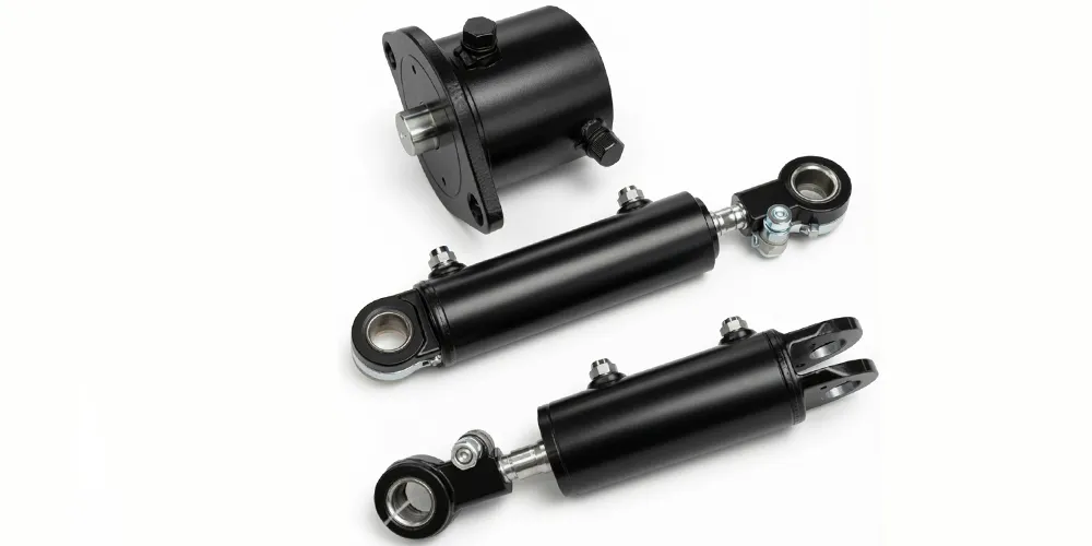
Kippzylinder
Our Tilt Cylinder range covers the angular positioning functions in crane outrigger, jib, and auxiliary systems that work alongside the main boom angle cylinder in a complete crane hydraulic circuit — matching the main boom angle cylinder's pressure and seal specification. Matched seal chemistry, chrome specification, and pressure class compatibility across the cylinder range allows crane maintenance teams to source all cylinder types from a single vendor, streamlining documentation, supplier qualification, and parts logistics across fleet maintenance programmes for French crane rental and contracting companies.
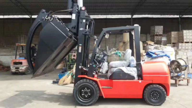
Gabelstapler-Hubzylinder
The forklift lifting cylinder range shares manufacturing standards, quality documentation practices, and pressure rating methodology with the truck crane cylinder series. For crane service companies and industrial facility operators who also manage forklift fleets for on-site material handling — a common combination at major French construction and petrochemical sites — single-vendor procurement for all hydraulic cylinder types simplifies supplier qualification and provides consistent technical documentation across the full cylinder inventory.
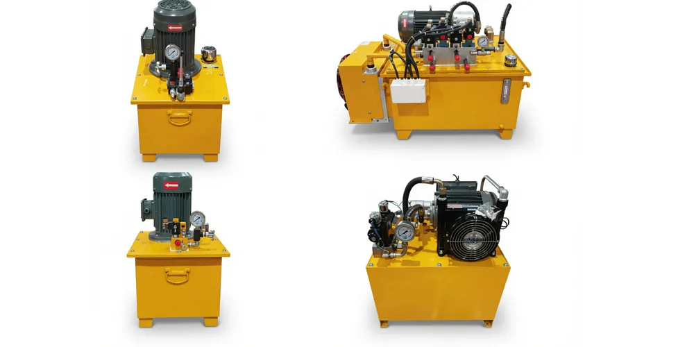
Hydraulic Pump Station
A matched hydraulic pump station provides the flow rate and system pressure required to operate the main boom angle cylinder and complementary crane circuit cylinders within their rated parameters. For crane refurbishment projects where the luffing cylinder and pump unit are both approaching service life limits, a matched station and cylinder replacement package eliminates separate hydraulic compatibility calculations and provides pre-verified system performance — reducing commissioning time and guaranteeing hydraulic performance from the first lift on the rebuilt crane.
10. About Us
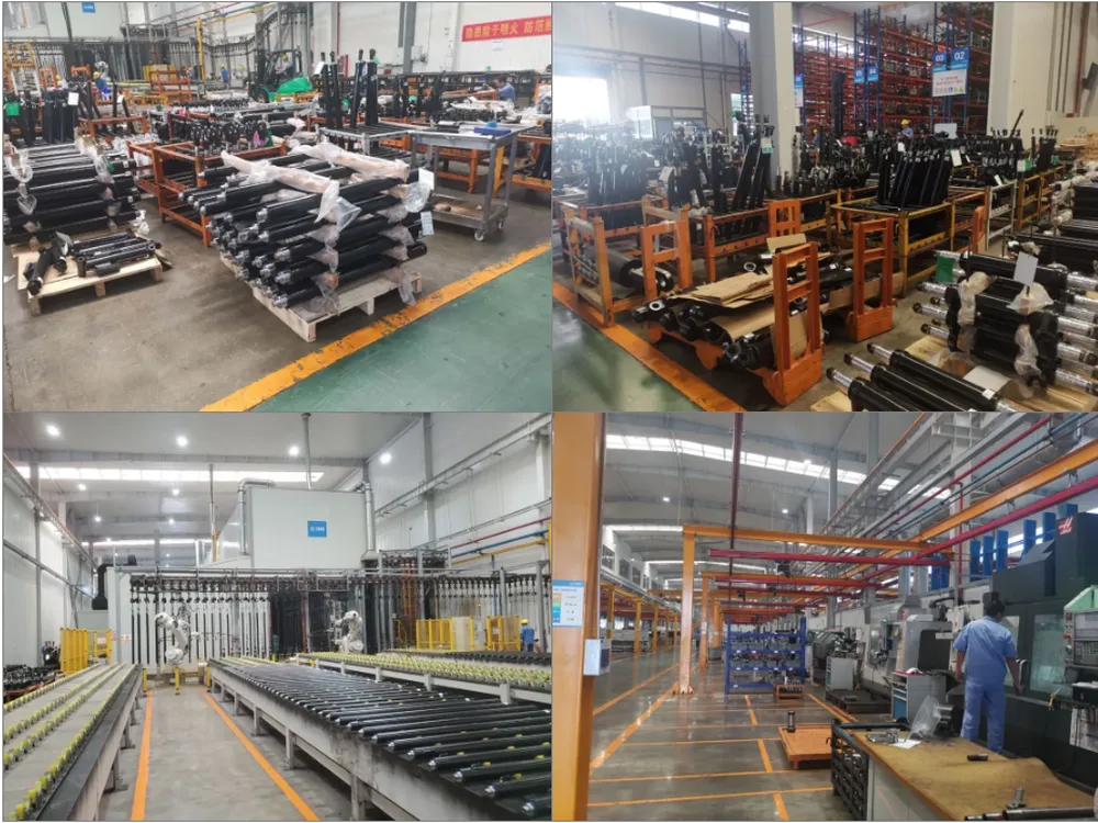
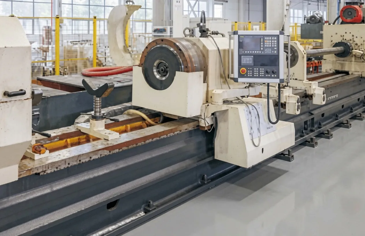
We are a specialist hydraulic cylinder manufacturer producing heavy industrial actuators and structural cylinders across a broad specification range — from compact double acting hydraulic cylinders for forklift accessories through large-bore, long-stroke main boom angle cylinders built for truck cranes of the scale described on this page. Our production capability encompasses deep-hole boring for large-bore barrel production, CNC precision honing for bore surface finish to Ra ≤ 0.4 µm, large-diameter chrome plating lines capable of processing 280 mm rods to 30 µm+ depth, structural welding qualified to EN 1090, and high-pressure hydraulic test benches capable of verifying the 39 MPa maximum withstand pressure on every unit individually before dispatch. ISO 9001:2015 quality management certification governs the complete manufacturing process from raw steel receipt through finished product release. The main boom angle cylinder material traceability documentation, weld procedure records, and unit test records we supply are prepared in the format required for crane operator technical files under EN 13000 and the French Arrêté du 1er mars 2004 crane inspection framework.
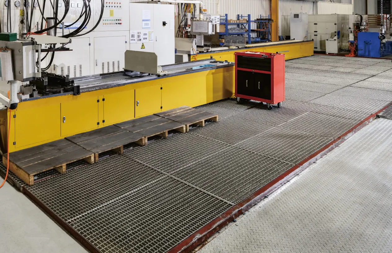
WorkShop
Request a Quote for the EP-Φ280×Φ250×3507 Main Boom Angle Cylinder for Your Crane Project
Whether you are a truck crane operator in France requiring a new or replacement main boom angle cylinder, a crane manufacturer specifying an OEM supply programme, or a maintenance contractor managing a fleet rebuild, our team can confirm availability, documentation package scope, and delivery lead time for your application. Provide your crane model or existing cylinder serial number for fastest cross-reference.
Frequently Asked Questions
Q1. What is a main boom angle cylinder on a truck crane and how does it control the boom elevation angle?
Q2. Where can I get a supplier quote for a main boom angle cylinder replacement for a truck crane operating on a French nuclear facility maintenance contract?
Q3. What is the barrel of a hydraulic cylinder and why does the barrel material specification matter for crane duty main boom angle cylinders?
Q4. What are the French and EU regulatory inspection requirements for main boom angle cylinder maintenance on truck cranes under the Arrêté du 1er mars 2004?
Q5. What documentation should I expect from hydraulic cylinder manufacturers when ordering a main boom angle cylinder for a crane with EN 13000 compliance requirements?
Q6. How does the main boom angle cylinder differ from a boom offset cylinder and which type does my truck crane use for luffing control?
Q7. What are the main failure modes of a main boom angle cylinder on a large truck crane in France and how can crane operators prevent premature failure?
Q8. Which hydraulic cylinder manufacturers in Europe can supply a main boom angle cylinder with complete EN 13000 documentation for a wind turbine installation project in northern France?
Q9. How much does a replacement main boom angle cylinder cost for a truck crane operating on bridge construction projects across the Île-de-France region?
Q10. What are the different types of hydraulic cylinders used in a truck crane and how does the main boom angle cylinder compare to the lift cylinder and other actuators?
Q11. When is it better to repair a main boom angle cylinder versus ordering a complete replacement unit for a crane currently on an active infrastructure project in Lyon or Marseille?
Editor: PXY