
Produktbeschreibung
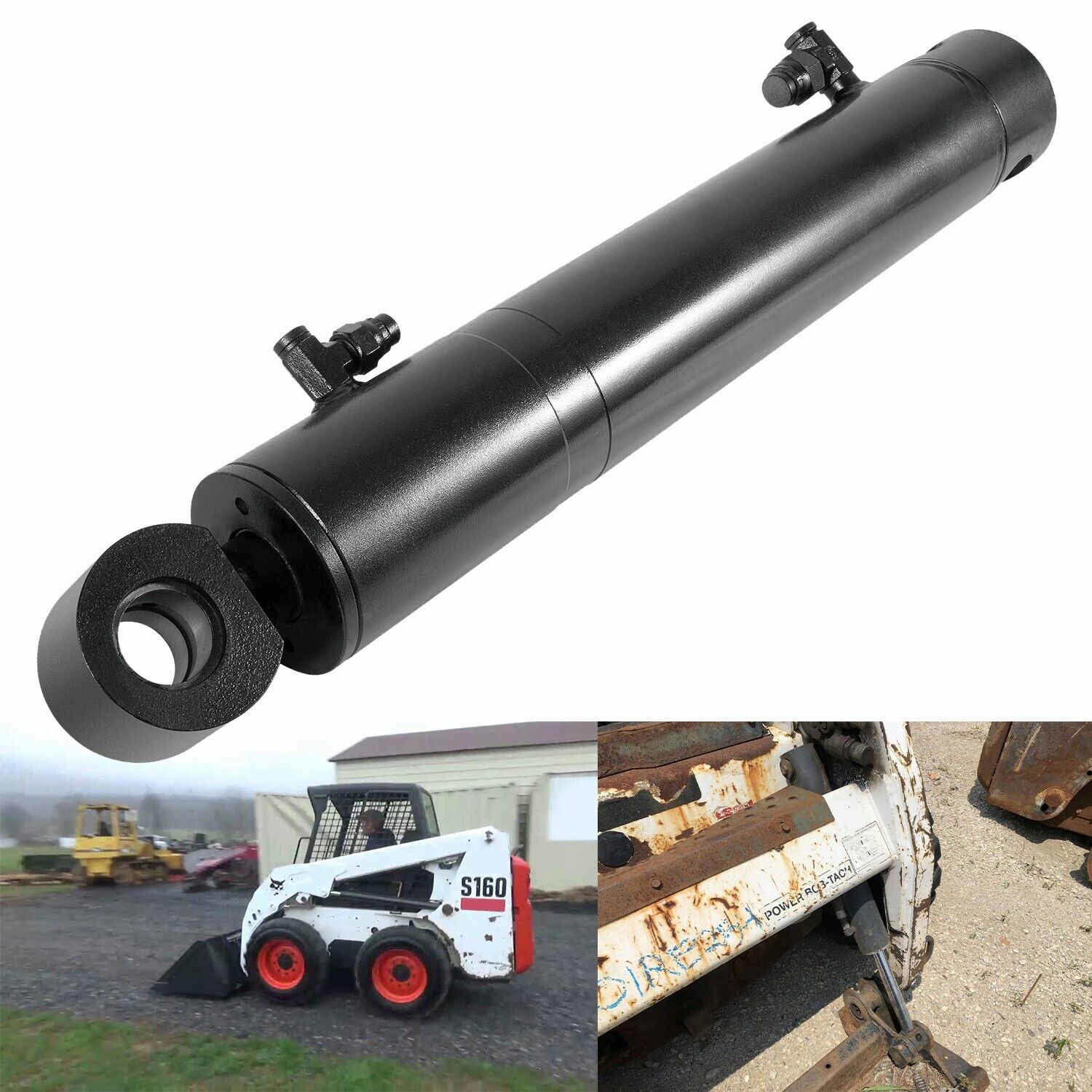
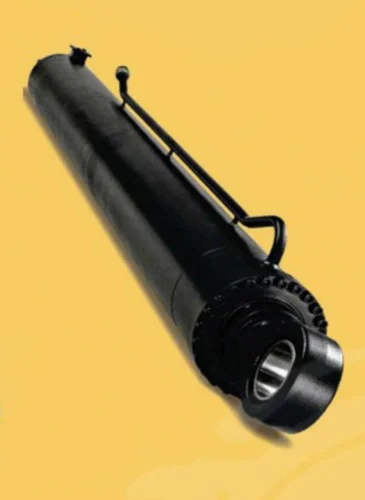
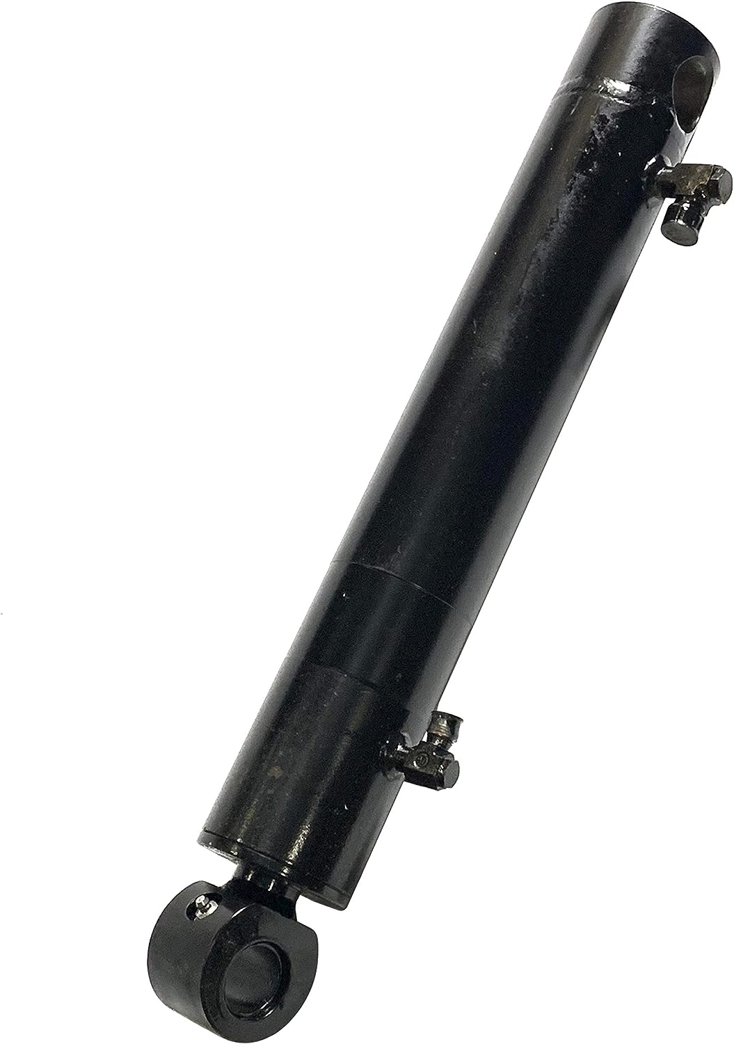
Special Design Widely Used Small Excavator Hydraulic Bucket Cylinder
Hydraulic Bucket Cylinder
A hydraulic bucket cylinder, or a hydraulic cylinder or hydraulic ram, is a mechanical device used in hydraulic systems to provide linear force and motion. It is commonly used in various applications, including construction, agricultural, and industrial machinery.
The hydraulic bucket cylinder is specifically designed for use in bucket attachments, such as those found on excavators, loaders, or backhoes. It is responsible for extending and retracting the bucket arm to control the movement of the bucket, allowing it to scoop, lift, and dump materials.
Applications of Hydraulikzylinder
Here are some key features and components of a hydraulic bucket cylinder:
Cylinder body: The cylinder body is a cylindrical tube that houses the piston and other internal components. It is typically made of durable and corrosion-resistant materials such as steel.
Piston: The piston is a cylindrical component that moves back and forth inside the cylinder body. It is sealed to create pressure chambers and divides the cylinder into 2 distinct areas: the rod side and the cap side.
Rod: The rod, also known as the piston rod or ram, is attached to the piston and extends through a seal at 1 end of the cylinder. It provides the linear motion and force required for the bucket arm movement.
Seals: Seals prevent hydraulic fluid leakage and maintain pressure within the cylinder. They are typically made of rubber or other elastomeric materials and are located at various points along the cylinder, including the piston and rod.
Ports: Hydraulic fluid enters and exits the cylinder through ports on the cylinder body. These ports are connected to the hydraulic system, allowing pressurized fluid to act on the piston and generate force.
Mounting points: Hydraulic bucket cylinders are typically mounted to the equipment’s frame or structure using specialized brackets. These brackets provide stability and support for the cylinder during operation.
The hydraulic bucket cylinder uses pressure to extend or retract the piston and rod. When pressurized fluid is supplied to the appropriate port, it causes the piston to move, extending or retracting the rod. This motion is transmitted to the bucket arm, enabling it to perform the desired actions.
How does a hydraulic bucket cylinder work?
A hydraulic bucket cylinder, or a hydraulic cylinder or hydraulic ram, is a mechanical device used in hydraulic systems to provide linear force and motion. It works on the principle of Pascal’s law, which states that when pressure is applied to a fluid in a confined space, the pressure is transmitted equally in all directions.
Here’s how a hydraulic bucket cylinder works:
1. Hydraulic fluid supply: The hydraulic system supplies pressurized hydraulic fluid, typically oil, to the hydraulic bucket cylinder through an inlet port. This fluid is usually stored in a reservoir and circulated by a pump.
2. Cylinder construction: The hydraulic bucket cylinder consists of a cylinder barrel, a piston, and a piston rod. The cylinder barrel is a cylindrical tube with sealed ends. The piston is a cylindrical component that fits tightly inside the cylinder barrel and divides it into 2 chambers: the rod side (head end) and the cap side (blind end). The piston rod extends from the piston and is attached to the bucket arm.
3. Fluid pressure application: When pressurized hydraulic fluid is supplied to the cylinder’s rod side (head end), it pushes against the piston, creating a force that extends the piston rod. The pressure is transmitted evenly across the piston, creating a balanced force.
4. Retraction: To retract the piston rod and move the bucket arm back, the hydraulic fluid is supplied to the cylinder’s cap side (blind end). The pressure from the fluid pushes against the opposite side of the piston, causing the piston rod to retract.
5. Control valves: The flow of hydraulic fluid to the cylinder is controlled by hydraulic control valves, which the equipment operator operates. These valves direct the flow of fluid to the appropriate side of the cylinder, enabling precise control of the bucket arm’s movement.
6. Sealing: Seals prevent hydraulic fluid leakage and maintain pressure within the cylinder. They are located at various points around the piston and piston rod to ensure a tight seal and prevent fluid from leaking out.
7. Force and motion: As the hydraulic fluid applies pressure to 1 side of the piston, it generates a force that extends or retracts the piston rod. This force is transmitted to the bucket arm, allowing it to move linearly and perform tasks such as scooping, lifting, and dumping materials.
Hydraulic bucket cylinders are widely used in construction machinery, agricultural equipment, and various industrial applications. They provide powerful and precise force transmission, making them essential components in hydraulic systems for heavy-duty tasks.
Our Company
We have a first-class independent R&D platform for assembly. The forklift cylinder production workshop has 4 semi-automatic lifting cylinder assembly lines and 1 fully automatic tilting cylinder assembly line, with a designed annual production capacity of 1 million pieces; the special cylinder workshop is equipped with semi-automatic cleaning and assembly systems of various specifications, with a designed annual production capacity of 200,000 essays. It has famous CNC machining equipment, machining centers, special equipment for high-precision cylinder processing, robot welding machines, automatic cleaning machines, automatic cylinder assembly machines, and automatic paint production lines. We have more than 300 sets of critical equipment running. The optimized allocation and efficient utilization of equipment resources ensure the precision requirements of the products and meet the high standard quality requirements of the products.
Forklift cylinder assembly shop | Other types of cylinder assembly shop |
Welding
Painting & coating
Painting & coating line | Fully automatic water-based |
Testing
To further improve product performance, and establish the leadership position of our hydraulic cylinder in the industry, our company and zjimee jointly established a Comprehensive performance laboratory of hydraulic cylinders, hydraulic valves, and hydraulic pumps; the lab is computer-assisted testing, using electro-hydraulic control technology, the test conditions preset by computer, which improves the test accuracy and system versatility, and the experimental data.
The automatic collection is realized through the application of sensors, and the output data, such as the internal leakage and load efficiency of the cylinder or the valve, are directly processed by the computer and converted to standard units (ml/min; %). At the same time, to ensure the working safety of the hydraulic system, the state monitoring function is carried out for key performance parameters, such as “oil temperature monitoring, liquid level monitoring, filter device monitoring,” etc. Among them, the hydraulic cylinder test stand can test the performance of “load efficiency” and “internal leakage” by readings. At the same time, it is equipped with a grating ruler measuring instrument, which meets the requirements of all test items of hydraulic cylinder products in the national standard.
Our Factory
Packaging & Shipping
| Zertifizierung: | GS, RoHS, CE, ISO9001 |
|---|---|
| Druck: | High Pressure |
| Betriebstemperatur: | Normale Temperatur |
| Schauspielweise: | Doppelt wirkend |
| Arbeitsweise: | Rotary |
| Angepasste Form: | Regulierter Typ |
Wie trägt ein Neigungszylinder zur präzisen Positionierung von Geräten bei?
Ein Neigezylinder spielt eine entscheidende Rolle für die präzise Positionierung von Geräten. Er liefert die notwendige Kraft und Kontrolle, um den Neigungswinkel des Geräts anzupassen und es dem Bediener so zu ermöglichen, es für verschiedene Aufgaben genau zu positionieren. Hier eine detaillierte Erklärung:
- Neigungswinkelverstellung: Ein Neigungszylinder ermöglicht es dem Bediener, den Neigungswinkel des Geräts anzupassen. Durch Betätigung des Zylinders kann das Gerät nach vorn oder hinten geneigt werden, was eine präzise Positionierung ermöglicht. Die Feinjustierung des Neigungswinkels erlaubt es dem Bediener, das Gerät auf bestimmte Ziele oder Arbeitsbereiche auszurichten und so optimale Genauigkeit und Effizienz zu gewährleisten.
- Lastverteilung: Eine präzise Positionierung der Ausrüstung ist für eine optimale Lastverteilung unerlässlich. Ein Neigungszylinder ermöglicht es dem Bediener, den Neigungswinkel so einzustellen, dass die Last gleichmäßig auf die Ausrüstung verteilt wird. Dies ist besonders wichtig beim Umgang mit ungleichmäßigen oder unausgewogenen Lasten. Durch die präzise Positionierung mittels Neigungszylindersteuerung kann der Bediener die Lastverteilung optimieren, die Belastung der Ausrüstung minimieren und die Stabilität im Betrieb verbessern.
- Konturanpassung: Bei bestimmten Anwendungen, wie z. B. der Geländemodellierung oder Erdbewegung, ist eine präzise Positionierung der Geräte unerlässlich, um sich den Geländekonturen anzupassen. Ein Neigungszylinder ermöglicht es dem Bediener, den Neigungswinkel des Geräts an die Neigung oder Form des Bodens anzupassen. Diese Konturanpassung gewährleistet einen gleichmäßigen Kontakt mit der Oberfläche, fördert eine gleichmäßige Planierung oder Aushubarbeit und erzielt präzise die gewünschten Ergebnisse.
- Höhenverstellung: Einige Neigezylinder ermöglichen neben der Neigungswinkelverstellung auch eine Höhenverstellung. Durch Aus- oder Einfahren des Zylinders können Bediener die Position des Geräts anheben oder absenken. Diese Höhenverstellung verbessert die präzise Positionierung und ermöglicht es dem Bediener, das Gerät für spezifische Aufgaben oder Arbeitsbedingungen auf die gewünschte Höhe auszurichten.
- Integration mit Steuerungssystemen: Neigezylinder lassen sich in moderne Anlagen mit fortschrittlichen Steuerungssystemen integrieren. Diese Systeme umfassen elektronische oder hydraulische Steuerungen, die eine präzise und automatisierte Neigungswinkelverstellung ermöglichen. Durch den Einsatz solcher Systeme erreichen Bediener eine hochpräzise und gleichmäßige Positionierung der Anlage, wodurch menschliche Fehler reduziert und die Gesamtproduktivität gesteigert werden.
- Bedienerfeedback: Mit Sensoren oder Rückmeldemechanismen ausgestattete Neigungszylinder liefern dem Bediener Echtzeitinformationen über den Neigungswinkel der Anlage. Dieses Feedback ermöglicht präzise Anpassungen und eine genaue Positionierung. Durch die kontinuierliche Überwachung des Neigungswinkels kann der Bediener die gewünschte Position während des Betriebs beibehalten und bei Bedarf Korrekturen vornehmen.
Ein Neigungszylinder trägt daher wesentlich zur präzisen Positionierung von Geräten bei, indem er die Einstellung des Neigungswinkels, die Optimierung der Lastverteilung, die Anpassung an Konturen, die Höhenverstellung, die Integration in Steuerungssysteme und die Rückmeldung an den Bediener ermöglicht. Diese Funktionen verbessern die Genauigkeit, Effizienz und Vielseitigkeit von Geräten in verschiedenen Branchen, darunter Bauwesen, Materialtransport, Landwirtschaft und weitere.
How does a tilt cylinder handle variations in tilt angle and load?
A tilt cylinder is designed to handle variations in tilt angle and load to ensure optimal performance and safe operation. It employs various mechanisms and features that allow it to adapt to different angles and loads. Here’s a detailed explanation:
- Adjustable Force and Stroke: Tilt cylinders can be adjusted to accommodate variations in tilt angle and load. The force generated by the cylinder can be controlled by adjusting the hydraulic pressure, allowing for precise control over the tilting movement. Similarly, the stroke length of the cylinder can be customized to provide the desired range of motion, enabling flexibility in achieving different tilt angles.
- Flow Control Valves: Tilt cylinders often incorporate flow control valves that regulate the speed and rate of hydraulic fluid flow. These valves allow operators to adjust the flow rate, providing finer control over the tilting movement. By adjusting the flow control valves, operators can handle variations in tilt angle and load with greater precision and stability.
- Load-Sensing Technology: Some advanced tilt cylinders utilize load-sensing technology to automatically adjust the force output based on the load applied. Load sensors integrated into the cylinder or the hydraulic system provide real-time feedback on the load, enabling the cylinder to adjust its force accordingly. This ensures consistent and safe operation, even when dealing with varying loads.
- Structural Integrity: Tilt cylinders are designed with robust construction to handle variations in load. The materials used, such as high-strength steel, provide structural integrity and durability. The cylinder’s design considers factors such as bending moments and stress distribution to ensure safe operation under different load conditions.
- Seals and Lubrication: Tilt cylinders incorporate seals and lubrication systems to minimize friction and maintain the required performance. Seals prevent leakage and contamination, ensuring the hydraulic system operates efficiently. Proper lubrication reduces wear and tear on moving parts, allowing the cylinder to handle variations in tilt angle and load smoothly and reliably.
- Stability and Balance: Tilt cylinders are designed to maintain stability and balance during tilting operations. The cylinder’s attachment points, along with the equipment’s center of gravity, are carefully considered to ensure safe and controlled tilting. This helps prevent instability or tipping when facing variations in tilt angle or load.
By incorporating adjustable force and stroke, flow control valves, load-sensing technology, robust construction, seals and lubrication, as well as ensuring stability and balance, tilt cylinders can effectively handle variations in tilt angle and load. These features enable precise control, safe operation, and reliable performance in a wide range of applications across industries.
Können Sie die Rolle der Hydraulikflüssigkeit in einem Kippzylinder erklären?
Hydraulikflüssigkeit spielt eine entscheidende Rolle im Betrieb eines Kippzylinders. Sie ist ein essentielles Medium, das die Kraftübertragung ermöglicht und die Bewegung des Zylinders steuert. Hier eine detaillierte Erklärung der Funktion der Hydraulikflüssigkeit in einem Kippzylinder:
- Kraftübertragung: Hydraulikflüssigkeit überträgt die Kraft vom Hydrauliksystem auf den Kippzylinder. Das Hydrauliksystem setzt die Flüssigkeit unter Druck, wodurch ein hydraulischer Druck entsteht, der auf die Kolbenoberfläche wirkt. Dieses Druckungleichgewicht erzeugt eine Kraft, die den Kolben bewegt und dadurch die Kolbenstange des Kippzylinders aus- oder einfährt. Die durch die Hydraulikflüssigkeit übertragene Kraft ermöglicht das kontrollierte Kippen des angeschlossenen Bauteils in schweren Maschinen.
- Durchflussregelung: Die Hydraulikflüssigkeit steuert den Kraftfluss im Kippzylinder. Das Hydrauliksystem verwendet Steuerventile, um Durchfluss und Richtung der Flüssigkeit zu regulieren. Durch die Einstellung der Ventilstellung kann der Bediener Geschwindigkeit, Richtung und Ausmaß der Kippbewegung steuern. Dieser Durchflussregelungsmechanismus ermöglicht die präzise Positionierung und Justierung des gekippten Bauteils entsprechend den jeweiligen Aufgabenanforderungen.
- Druckregelung: Die Hydraulikflüssigkeit ermöglicht auch die Druckregelung im Kippzylinder. Das Hydrauliksystem verfügt über Druckregler oder Überdruckventile, um den gewünschten Druck aufrechtzuerhalten. Diese Ventile gewährleisten, dass der Hydraulikflüssigkeitsdruck im sicheren Betriebsbereich bleibt und verhindern so einen übermäßigen Druckaufbau, der den Zylinder oder andere Komponenten beschädigen könnte. Die Druckregelung trägt zum sicheren und effizienten Betrieb des Kippzylinders bei.
- Schmierung und Kühlung: Die Hydraulikflüssigkeit dient im Kippzylinder als Schmiermittel und reduziert die Reibung zwischen den beweglichen Teilen. Diese Schmierung minimiert den Verschleiß und verlängert die Lebensdauer des Zylinders. Zusätzlich absorbiert und leitet die Hydraulikflüssigkeit die im Betrieb entstehende Wärme ab und wirkt somit als Kühlmittel. Effektive Schmierung und Kühlung tragen wesentlich zur Gesamtleistung und Langlebigkeit des Kippzylinders bei.
- Abdichtung und Schutz vor Verunreinigungen: Hydraulikflüssigkeit trägt zur Aufrechterhaltung der Dichtheit der Hydraulikdichtungen des Kippzylinders bei. Sie dichtet zwischen Kolben und Zylinderwand ab und verhindert so das Austreten von Hydraulikflüssigkeit. Zudem schützt sie vor dem Eindringen von Verunreinigungen wie Schmutz, Ablagerungen oder Feuchtigkeit in den Zylinder und damit vor potenziellen Schäden. Diese Abdichtungs- und Schutzfunktion gewährleistet die einwandfreie Funktion und lange Lebensdauer des Kippzylinders.
Zusammenfassend lässt sich sagen, dass Hydraulikflüssigkeit in einem Kippzylinder eine vielschichtige Rolle spielt. Sie überträgt Kraft, steuert Durchfluss und Druck, sorgt für Schmierung und Kühlung, dichtet den Zylinder ab und verhindert Verunreinigungen. Durch den effektiven Einsatz von Hydraulikflüssigkeit ermöglicht der Kippzylinder das kontrollierte Kippen von Bauteilen in schweren Maschinen, gewährleistet so einen präzisen Betrieb und verbessert die Leistung und Zuverlässigkeit der Anlagen.


editor by CX 2023-12-09