
EP-Φ40×Φ20×200 Hydraulic Locking Cylinder
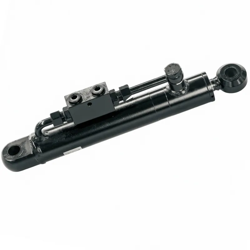
The EP-Φ40×Φ20×200 is a compact hydraulic locking cylinder designed for the cylinder series for environmental protection equipment. Unlike conventional hydraulic cylinders that rely on continuous oil pressure to maintain their extended or retracted position, a hydraulic locking cylinder with mechanical lock incorporates an integrated position-holding mechanism that physically locks the cylinder rod in place once the commanded position is reached. This means that even if hydraulic pressure is removed entirely — due to a pump shutdown, hose failure, or deliberate power-down during non-operational periods — the locked position is held by mechanical means rather than hydraulic pressure alone. At 4.2 kg and 370 mm installation distance, this small hydraulic cylinder is dimensioned for integration into compact environmental equipment across French and European waste management, water treatment, and hazardous materials handling applications.
Environmental Protection Cylinder Series
EP-Φ40×Φ20×200 Hydraulic Locking Cylinder
A compact double-acting hydraulic locking cylinder engineered for environmental protection equipment, refuse compactors, hazardous waste handling systems, and industrial locking applications where a mechanically locked position must be maintained without continuous hydraulic pressure. Model HCYY11112013, Φ40×Φ20×200 mm, rated at 30 MPa working pressure and 37 MPa maximum withstand pressure, 200 mm stroke, 370 mm installation distance, 4.2 kg. Trusted by environmental equipment manufacturers and OEM engineers across France and the European Union.
Key Technical Facts
HCYY11112013
Φ40 mm
Φ20 mm
200 mm
30 MPa
37 MPa
370 mm
4.2 kg
1. Technical Specifications — EP-Φ40×Φ20×200 Hydraulic Locking Cylinder
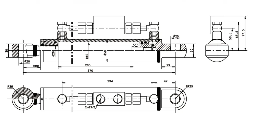
Model: HCYY11112013. Specification: Φ40 × Φ20 × 200 (bore × rod × stroke, all in mm). Mounting: knuckle eye both ends. Application: environmental protection equipment cylinder series.
| Parameter | Value | Notes |
|---|---|---|
| Cylinder Model | HCYY11112013 | OEM part number, environmental protection cylinder series |
| Specification | Φ40 × Φ20 × 200 | Bore Φ40 mm, rod Φ20 mm, stroke 200 mm |
| Working Pressure | 30 MPa | Rated continuous operating pressure (300 bar) — above standard industrial cylinder range |
| Maximum Withstand Pressure | 37 MPa | Static proof pressure (370 bar); safety factor 1.23 over working pressure |
| Stroke (Trip) | 200 mm | Total rod travel from fully retracted to fully extended position |
| Installation Distance | 370 mm | Pin-to-pin center distance in reference installation position |
| Weight | 4.2 kg | Unit weight including integrated lock mechanism, without hydraulic fluid |
| Cylinder Type | Double acting hydraulic cylinder with mechanical lock | Active hydraulic force in both extend and retract; mechanical lock holds any intermediate or end position |
| Mounting | Knuckle eye (clevis) both ends | Pin-joint connection allowing angular accommodation across stroke arc |
| Lock Mechanism | Integrated hydraulic cylinder rod locking device | Spring-engage / hydraulic-release; fail-safe locks on pressure loss |
| Push Force at Working Pressure | Approx. 37.7 kN | π × 20² × 30 MPa = 37.7 kN at full bore area |
| Application Series | Environmental protection equipment | Refuse compactors, filter presses, waste crushers, water treatment equipment |
2. What Is a Hydraulic Locking Cylinder?
A hydraulic locking cylinder is a specialized hydraulic actuator that combines the linear force and speed control capabilities of a conventional hydraulic cylinder with an integrated mechanical position-holding device — the lock mechanism — that physically prevents rod movement once the cylinder has reached its commanded position. The defining characteristic that distinguishes a hydraulic locking cylinder from a standard double acting hydraulic cylinder is this ability to hold position without any hydraulic pressure. In a standard hydraulic cylinder, removing pressure from both ports allows the rod to drift under load; in a hydraulic locking cylinder, a spring-loaded or hydraulically-released locking collar, jaw, or pin engages the rod or barrel the moment hydraulic pressure is reduced, mechanically clamping the cylinder at its current position until an active hydraulic release signal is deliberately applied.
In the context of the environmental protection equipment series this hydraulic locking cylinder belongs to, the locking function addresses a specific operational safety requirement: environmental processing machinery — refuse compactors, bale presses, hazardous waste crushers, and filter press clamping systems — frequently needs to hold a mechanical position under sustained force loads during a process cycle that may last minutes to hours. Requiring continuous hydraulic pressure throughout this hold period wastes pump energy, generates heat, and stresses seals unnecessarily. The hydraulic cylinder safety lock function allows the hydraulic system to be depressurized immediately after the position is reached, with the mechanical lock bearing all position-holding loads while the pump cycles off. This is precisely the operating mode mandated by energy efficiency standards and noise regulations applicable to French waste management facilities under French environmental legislation and EU Ecodesign directives.
The EP-Φ40×Φ20×200 hydraulic locking cylinder is classified as a compact hydraulic locking cylinder at 4.2 kg unit weight and 200 mm stroke, but its 30 MPa working pressure rating — substantially above the 16-25 MPa typical of general industrial cylinders — means the force output from the Φ40 mm bore area of 1,257 mm² reaches approximately 37.7 kN at working pressure, with the locking device holding this hydraulic locking cylinder force mechanically once the position is established. This combination of compact physical dimensions, high pressure rating, and integral mechanical lock makes this hydraulic locking cylinder the preferred solution for environmental equipment designers in France and across the EU who need reliable position-holding in constrained machine frame spaces where there is no room for a separate external lock mechanism or brake device.
3. Five Key Product Advantages
Mechanical Lock Eliminates Continuous Pressure Requirement for Position Holding
The integrated mechanical locking device allows the hydraulic system to be fully depressurized once the hydraulic locking cylinder reaches its commanded position, with the lock bearing all position-holding force loads independently of the hydraulic circuit. This eliminates the energy waste and heat generation of continuous pressure maintenance during long process dwell periods — a critical operational advantage in French environmental facilities governed by energy efficiency requirements under the EU Ecodesign Regulation and French ADEME sustainability guidelines for industrial waste processing equipment.
30 MPa High Working Pressure in a Compact 4.2 kg Body
This hydraulic locking cylinder force-to-weight ratio is particularly valuable in environmental equipment where machine frame weight and compactness directly affect the vehicle payload capacity of mobile refuse collection vehicles and waste treatment trailers serving French municipal waste management contracts. The 30 MPa working pressure rating is substantially higher than the 16-25 MPa range of standard industrial cylinders at this bore size, delivering approximately 37.7 kN push force from a Φ40 mm bore in a 4.2 kg package that occupies only 370 mm of installation distance.
37 MPa Maximum Withstand Pressure — 23% Safety Margin Over Working Pressure
The 37 MPa maximum withstand pressure provides a 23% safety margin above the 30 MPa working pressure, accommodating hydraulic pressure spikes generated by pump over-pressure events, sudden load release, or emergency valve activation in environmental processing equipment. This safety margin exceeds the minimum 1.5x proof pressure requirement of ISO 10100, which this hydraulic locking cylinder satisfies, and supports compliance with EN ISO 4413 hydraulic safety standards applicable to fluid power systems incorporated in machinery placed on the French and EU market under the Machinery Directive.
Fail-Safe Mechanical Lock Provides Inherent Safety Against Hydraulic Failure
Because the locking device engages passively — either spring-loaded engagement or hydraulic-release disengagement — a loss of hydraulic pressure due to hose failure or pump shutdown automatically engages the hydraulic locking cylinder locked condition rather than allowing uncontrolled cylinder movement. This fail-safe behavior is a fundamental hydraulic cylinder safety lock requirement in French environmental facility safety plans (PPAM plans under ICPE regulations) and EU Machinery Directive Annex I requirements for machinery hydraulic systems where uncontrolled movement of actuators would create risks to personnel or environmental integrity.
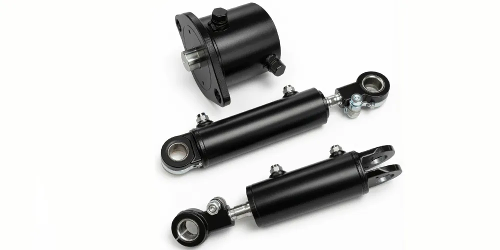
Knuckle Eye End Mounting for Multi-Axis Alignment in Compact Equipment
Both cylinder ends are fitted with knuckle eye (clevis) mounting heads visible in the product photograph, allowing pin-joint connection that accommodates angular misalignment between the cylinder axis and the driven component axis across the full 200 mm stroke arc. This mounting flexibility simplifies hydraulic locking cylinder installation in the compact, irregularly-shaped equipment frames typical of French municipal waste handling machines, industrial filter presses, and environmental processing units where precise coaxial alignment between the cylinder and load attachment points cannot always be guaranteed in welded fabrication structures.
4. How Does a Hydraulic Locking Cylinder Work?
How does a locking hydraulic cylinder work? The operating cycle of this hydraulic locking cylinder involves three distinct phases: active extension or retraction under hydraulic power, mechanical lock engagement, and hydraulic lock release for subsequent movement. During the extension phase, hydraulic oil at up to 30 MPa is delivered to the cap-end port of the double acting hydraulic cylinder, pushing the piston and Φ20 mm rod outward through the 200 mm stroke against the driven load — a bale press ram, filter plate clamp, or waste crusher jaw, depending on the specific environmental equipment application. The double acting configuration means that retraction is equally powered: hydraulic oil directed to the rod-end port pulls the piston back, giving the machine control authority over both directions of cylinder motion at all times.
How does a self locking hydraulic cylinder work at the mechanical level? Once the hydraulic control valve is centred to stop hydraulic locking cylinder movement at the commanded position, the integrated hydraulic cylinder rod locking device — which in the spring-engage design is continuously tensioned by a heavy compression spring — automatically clamps against the rod or barrel to prevent any further movement. The spring provides the clamping force directly proportional to the spring preload, meaning the lock engages immediately and does not require a separate electrical or hydraulic signal to activate. To release the lock and allow subsequent cylinder movement, a small secondary hydraulic pressure signal is directed to the lock release port, compressing the spring through a hydraulic piston within the lock housing and freeing the rod to move under main circuit pressure again. This two-port architecture — main circuit plus lock release — is visible in the product photograph as the secondary fitting assembly visible on the cylinder body between the rod gland and the cap end.
What is a lock cylinder in the hydraulic system context? The hydraulic locking cylinder is an actuator that provides both the motion and the position-holding functions that would otherwise require separate devices — a cylinder for motion plus an external brake, clamp, or counter-balance valve for position holding. The hydraulic lock built into this hydraulic locking cylinder eliminates the hydraulic cylinder lock valve that would otherwise be required to prevent load-induced drift in a standard cylinder. While a counterbalance valve or pilot-operated check valve addresses the hydraulic leakage-driven drift problem in standard cylinders, it still relies on hydraulic pressure to maintain the locked condition; the mechanical lock in this hydraulic locking cylinder holds the position entirely by mechanical means, providing a fundamentally more reliable and energy-efficient position-holding solution in each hydraulic locking cylinder for the environmental equipment applications across French waste management and water treatment sectors.
5. Hydraulic Cylinder Components and Materials
The material specification and manufacturing process of each hydraulic cylinder component determines the pressure integrity, locking reliability, and service life of the assembled EP-Φ40×Φ20×200 hydraulic locking cylinder in demanding environmental equipment operating conditions.
Cylinder Barrel
Seamless cold-drawn steel tube, precision-honed on the internal bore to Ra 0.4 micrometer to provide the seal contact surface for the piston seals at 30 MPa working pressure. For the hydraulic locking cylinder barrel, seamless construction eliminates longitudinal weld seams that would be potential fatigue crack initiation sites under the high cyclic pressure loading of refuse compactor and filter press operation. The external surface is black phosphate or enamel coated to resist the corrosive environments of French environmental facilities where hydraulic locking cylinder surfaces may be exposed to acidic leachate, fermentation gas, or saline cleaning fluids used in municipal waste processing and water treatment plants.
Piston Rod
The Φ20 mm rod is produced from 40Cr alloy steel bar, induction-hardened to HRC 52-58 at the rod surface, precision-ground to h6 tolerance, and hard chrome plated to a minimum 20 micrometer chrome depth. At 30 MPa working pressure, the hydraulic locking cylinder rod is subject to compressive Euler buckling risk at full extension that must be verified against the rod slenderness ratio for the 200 mm stroke. The 40Cr steel and chrome plating combination provides the combined buckling strength, surface wear resistance, and corrosion protection required for the hydrogen sulphide and ammonia-containing atmospheres present in French biogas, composting, and leachate treatment facilities where this hydraulic locking cylinder is commonly specified.
Piston and High-Pressure Seals
The piston is machined from alloy steel with precision-ground outer diameter and seal grooves machined to DIN 3869 standard dimensions for the O-ring and backup ring combination used at 30 MPa service pressure. At this elevated pressure level, the piston seal assembly uses PTFE-backed polyurethane seals or high-durometer NBR O-rings with PTFE anti-extrusion backup rings to prevent seal extrusion into the small clearance gap between the piston and bore at maximum pressure — a failure mode that is avoided at lower pressures but becomes critical above approximately 25 MPa where the seal material begins to yield under the radial pressure force at the clearance gap edge.
Integrated Mechanical Locking Device
The hydraulic cylinder rod locking device on this hydraulic locking cylinder is assembled from precision-machined spring housing, collet or jaw locking elements in hardened alloy steel or tool steel, and a hydraulic release piston. The spring force required to maintain the mechanical lock under the full cylinder force load of approximately 37.7 kN is engineered to the spring rate and preload of the specific lock design, ensuring the clamping friction on the rod provides the required position-holding force coefficient against the maximum applied load without slippage. Spring and locking element materials are heat treated and surface-treated for chemical resistance to the aggressive fluid environments present in environmental equipment applications across French waste management and industrial treatment sites.
End Eye Mounting Hardware
Both knuckle eye end fittings are machined from medium-carbon steel and heat treated for strength before finish-machining of the pin bore and mounting face. The pin-joint mounting configuration allows up to 3-5 degrees of angular accommodation between the cylinder axis and the attachment pin axis, compensating for the accumulated dimensional tolerances of welded environmental equipment frames where precise alignment of the cylinder mounting brackets cannot always be achieved within the same accuracy level as machined components in conventional machine tools. The pin bore is finished to H7 tolerance for a running clearance fit with the hardened mounting pin.
5. Hydraulic Locking Cylinder Procurement: Specification, Comparison, and Installation Guidance
Specifying the correct hydraulic locking cylinder for any environmental equipment project requires working through three sequential decisions: confirming the required force output against the application load, verifying that the hydraulic locking cylinder bore and stroke dimensions fit within the available installation envelope, and selecting the hydraulic locking cylinder lock mechanism variant that matches the machine's fail-safe philosophy. Each decision stage produces a narrowed candidate list, and the correctly specified hydraulic locking cylinder will fit the machine frame, generate the required position-holding force, and behave correctly under all foreseeable fault conditions without requiring design modification at the prototype stage.
Comparing each hydraulic locking cylinder against standard cylinder alternatives — counterbalance valve arrangements, pilot-operated check valve systems, or external mechanical brakes — reveals a consistent pattern: for process dwell times exceeding approximately 30 seconds under sustained load, the energy and maintenance cost advantage of a hydraulic locking cylinder becomes measurable in French facility operating cost analyses. The hydraulic locking cylinder avoids continuous pump run-time and seal cycling from maintained pressure; the counterbalance valve alternative requires constant pressure maintenance and generates proportional heat load in the hydraulic fluid throughout the dwell period. For French environmental facilities operating under EU Ecodesign requirements or ISO 14001 certified environmental management systems, this distinction regularly influences the hydraulic locking cylinder specification and makes the hydraulic locking cylinder the preferred solution at the machine design stage.
Installing a hydraulic locking cylinder correctly on first assembly is critical to achieving rated lock performance for each hydraulic locking cylinder to achieving rated lock performance. The hydraulic locking cylinder must be mounted with the lock release port accessible for hose connection and future servicing, the knuckle eye pins must be aligned to prevent binding across the stroke arc, and the hydraulic locking cylinder secondary lock release circuit must be configured so that lock release pressure is always applied before main circuit pressure to prevent pressure locking of the rod. These installation requirements are standard in the assembly documentation provided with the hydraulic locking cylinder and should be reviewed during the machine design phase so that hose routing and port access are incorporated into the equipment frame design from the outset.
6. Application Scenarios — Environmental Protection Equipment in France and Europe
The EP-Φ40×Φ20×200 hydraulic locking cylinder is designed for the following primary application environments within the environmental protection equipment sector across France and the European Union.
Municipal Refuse Compactor Clamping
Rear-loading refuse compactors and side-loading waste collection vehicles fitted with a hydraulic locking cylinder and used by French municipal sanitation services (services de collecte des dechets) across Paris, Lyon, Marseille, and Bordeaux metropolitan areas use hydraulic locking cylinders to clamp the compaction plate in its retracted position during transport between collection points. Without a mechanical lock, the compaction plate must be held by continuous hydraulic pressure from the vehicle hydraulic pump running continuously while driving — wasting fuel and generating cab heat. The hydraulic cylinder transport lock function of this cylinder allows the pump to be shut off between collection stops while the compaction plate is mechanically secured against road vibration-induced drift.
Industrial Filter Press Plate Clamping
Industrial filter presses used in French water treatment plants (stations d epuration) and industrial wastewater processing facilities require that the filter plate stack be clamped under sustained compressive force for filtration cycle durations of 30 minutes to several hours. A standard hydraulic cylinder would require the pump to run continuously throughout the cycle. The hydraulic locking cylinder with mechanical lock clamps the plate stack at the required position and allows the pump to de-energize completely, reducing energy consumption and noise levels at treatment plant sites located in proximity to French residential areas under environmental noise regulations (arrete du 25 janvier 2011).
Waste Baling Press Ram Lock
Stationary and mobile waste baling presses used by French recycling facilities and material recovery centers use a hydraulic locking cylinder to hold the bale compression ram at its final compaction position while the bale is being tied or strapped. During the 15-30 second bale strapping cycle, maintaining ram position under full baling force requires either continuous pump pressure or a mechanical lock. The hydraulic cylinder safety lock function of this hydraulic locking cylinder supports the baler strapping cycle without the need for a separate mechanical brake on the ram.
Hazardous Waste Container Lid Locking
A hydraulic locking cylinder is used in hazardous waste handling systems at French ICPE (Installations Classees pour la Protection de l Environnement) regulated sites to lock the lids of sealed waste containers during transport, processing, or transfer operations where accidental lid opening would release toxic, radioactive, or pathogenic materials. The fail-safe mechanical engagement of the lock ensures that the lid cannot be opened accidentally even during a hydraulic system failure event, providing the inherent safety that is required by French environmental safety regulations for ICPE Class A (highest risk) installations handling hazardous industrial waste.
Biogas and Anaerobic Digestion Plant Valve Actuation
Biogas plants (methaniseurs) at French agricultural sites and urban waste treatment centers use hydraulic actuators to control gas-tight valves and sluice gates in the digestion and gas conditioning systems. Each hydraulic locking cylinder provides the positive valve-open or valve-closed position retention needed for safe gas containment. A correctly specified hydraulic locking cylinder allows the hydraulic power unit to remain de-energized between valve position changes. The corrosion resistance of the cylinder external surfaces is particularly important in biogas environments where hydrogen sulphide concentrations can reach 2,000-5,000 ppm in the gas phase above the digestion liquid surface.
Leachate Treatment Equipment Clamping
Membrane filter systems and centrifuge cover-locking mechanisms at French landfill leachate treatment facilities rely on a hydraulic locking cylinder for the cover retention function. Leachate is an aggressive chemical mixture of organic acids, ammonia, heavy metal salts, and volatile organic compounds that attacks standard carbon steel and rubber seals — the hydraulic locking cylinder selected for this environment must have external body coating and seal material rated for chemical resistance to leachate-class fluids. The small hydraulic cylinder dimension of this unit fits within the compact equipment housings used in modular French leachate treatment containerized systems installed at municipal landfill sites across France.
7. Regulatory Standards and Compliance — France and European Union
Each hydraulic locking cylinder used in environmental protection equipment must comply with applicable safety and environmental standards in France and the EU. The following regulatory framework covers the primary requirements for this cylinder in its intended applications.
EN ISO 4413:2011 — Hydraulic Fluid Power — General Rules and Safety Requirements: This European harmonized standard establishes the safety requirements for hydraulic fluid power systems and their components, including hydraulic cylinders. Section 5.3 of EN ISO 4413 covers the requirements for preventing unintended machine actuator motion — a requirement directly addressed by the mechanical lock of the hydraulic locking cylinder. Systems incorporating actuators that must hold position against applied loads under any fault condition are required to use positive mechanical locking, for which this hydraulic locking cylinder provides a unified solution. Equipment incorporating this hydraulic locking cylinder must document compliance with EN ISO 4413 in the hydraulic circuit design documentation submitted to notified bodies for CE marking under the EU Machinery Directive.
EU Machinery Directive 2006/42/EC and Machine Regulation (EU) 2023/1230: Environmental processing machinery incorporating a hydraulic locking cylinder as a safety-relevant actuator falls under the Machinery Directive CE marking requirements. Annex I Section 4.1.2 specifically requires that hydraulic systems of machinery incorporate means of preventing hazardous movement of actuators when hydraulic pressure is lost — which is addressed by the fail-safe lock engagement of this cylinder. The new Machine Regulation 2023/1230, effective January 2027, updates these requirements and introduces enhanced documentation requirements for fluid power safety components that will require hydraulic locking cylinder manufacturers to provide additional performance data on lock holding capacity and failure modes.
French ICPE Regulation — Installations Classees pour la Protection de l Environnement: Environmental processing facilities in France operating under ICPE classification must comply with arretes prefectoraux that specify safety requirements for equipment handling hazardous substances. Hydraulic systems on ICPE Class A and B installations are subject to inspection by DREAL inspectors who verify that actuators controlling safety-critical positions incorporate appropriate fail-safe position holding. The mechanical lock of this cylinder satisfies this requirement under ICPE inspection criteria.
ISO 10100:2020 — Hydraulic Fluid Power Cylinders — Dimensions and Tolerances: The bore, rod, and gland dimensional standards that ensure interchangeability and quality consistency of hydraulic cylinders across the European supply chain. The Φ40 bore and Φ20 rod of this cylinder fall within the standard dimension series of ISO 10100, supporting replacement procurement by French environmental equipment maintenance organizations without need for custom sourcing or dimensional verification beyond the key installation measurements.
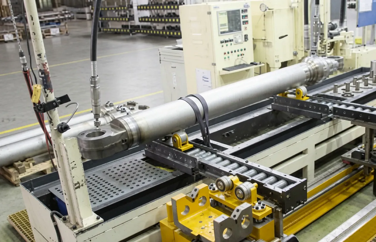
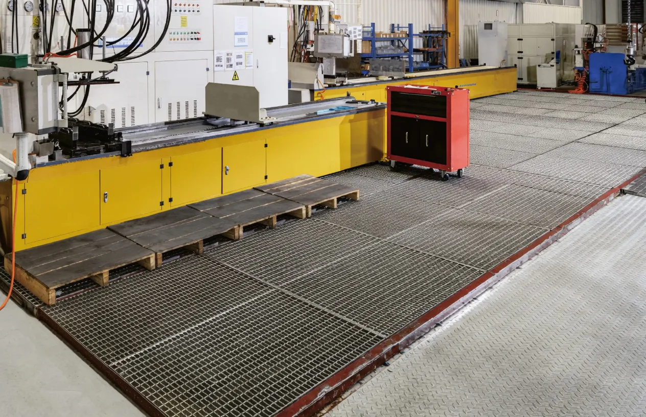
8. About Us
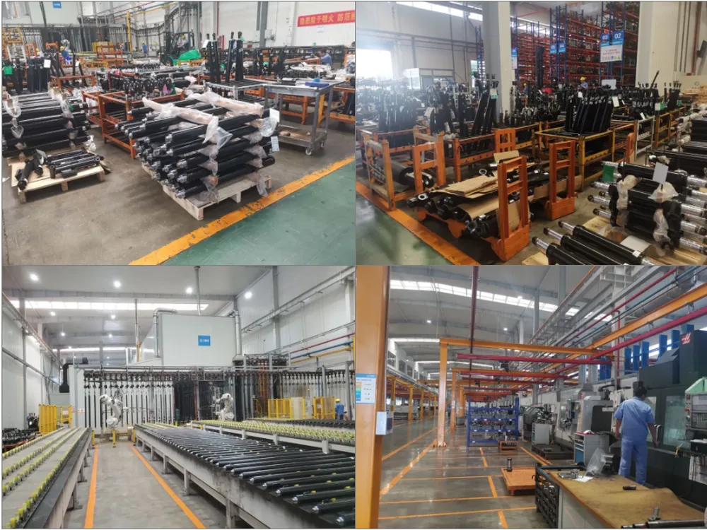
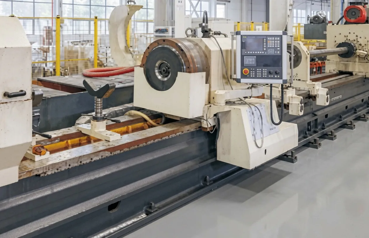
We are a professional manufacturer of hydraulic cylinders for environmental protection equipment, industrial machinery, and mobile equipment, specializing in custom and standard hydraulic cylinder production including the hydraulic locking cylinder in single and multiple configurations alongside double acting hydraulic cylinders, forklift tilt cylinders, lifting cylinders for aerial work vehicles, and telescopic hydraulic cylinders. Our production facility is equipped with CNC honing machines, hard chrome rod plating lines, high-pressure seal assembly stations, and automated leak test equipment for 100% hydrostatic testing of the hydraulic locking cylinder and related components at rated working pressure before dispatch.
WorkShop
9. Compatible Products — Complete Environmental Equipment Hydraulic System
The hydraulic locking cylinder is one component in a complete machine hydraulic circuit. Procuring the hydraulic locking cylinder alongside compatible components simplifies project supply. We supply hydraulic system components for one-stop procurement in environmental and industrial equipment projects across France and the EU.
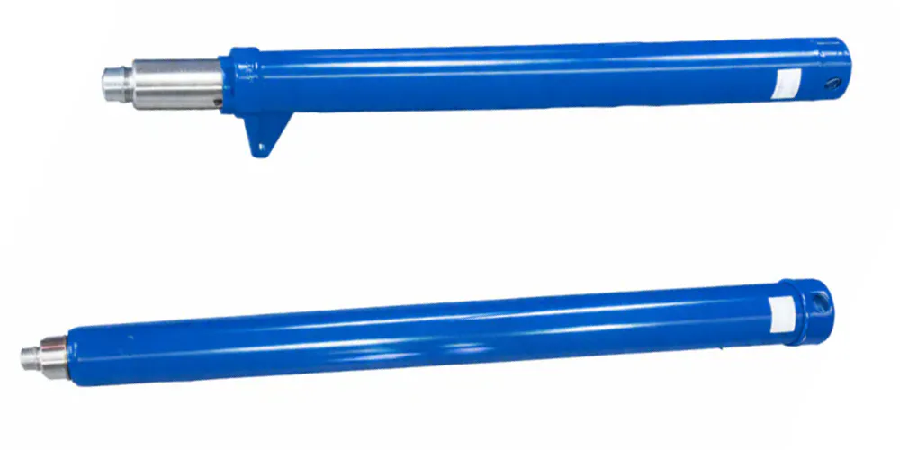
Tilt Cylinder Series
Environmental vehicles and equipment often require both a hydraulic locking cylinder for position-holding functions and standard Tilt Cylinders for dynamic motion control of tipping bodies, articulated arms, and equipment positioning circuits. Our complete tilt cylinder range covers double-acting configurations in bore sizes from Φ40 through Φ120 mm for environmental vehicle and construction equipment applications across the French and European market, with documentation standards compatible with the CE marking files used for the environmental protection equipment cylinder series that this hydraulic locking cylinder belongs to.
Forklift Lifting Cylinder
Organizations procuring a hydraulic locking cylinder for environmental equipment often also maintain fleets of forklifts and material handling vehicles used to transport waste containers, recycling bales, and process materials within their facilities. Our Forklift Lifting Cylinder range covers single-acting and double-acting designs for counterbalanced forklifts, reach trucks, and order pickers in bore sizes from Φ50 through Φ120 mm. Sourcing both the hydraulic locking cylinder and forklift lifting cylinders from the same hydraulic cylinder manufacturer simplifies supplier qualification, technical documentation management, and after-sales parts supply across French environmental facility operations.
Hydraulic Pump Station
The hydraulic pump station provides the 30 MPa pressure supply matched to the hydraulic locking cylinder main circuit and the secondary lock release circuit. Our pump station units configured for environmental equipment include AC electric motor versions for fixed plant installations at French treatment facilities, and DC battery-powered versions for mobile refuse collection vehicles and portable environmental monitoring equipment. Selecting the pump station and hydraulic locking cylinder from the same supplier ensures that the pump pressure setting, flow rate, and hydraulic oil specification are matched to the cylinder operating requirements without the circuit adjustment work that arises from combining components from incompatible suppliers.
Frequently Asked Questions
Q1. What is a hydraulic locking cylinder and how does it differ from a standard double acting hydraulic cylinder used in French industrial equipment?
A hydraulic locking cylinder combines a standard double-acting cylinder body with an integrated mechanical locking device that physically prevents rod movement once the cylinder reaches a commanded position, even when hydraulic pressure is completely removed. A standard double acting hydraulic cylinder only holds position as long as hydraulic pressure is maintained in the sealed circuit — any seal leakage, pilot-operated check valve drift, or hydraulic supply loss allows gradual or sudden position change. The mechanical lock inside the hydraulic locking cylinder holds the position by mechanical clamping force alone, making it the appropriate specification for French environmental equipment where fail-safe position retention under all fault conditions is a regulatory requirement under ICPE safety plans.
Q2. How does a locking hydraulic cylinder work when the hydraulic pressure supply is interrupted at a French waste processing facility?
When hydraulic pressure supply is interrupted to a locking hydraulic cylinder — whether from pump shutdown, hose failure, or emergency stop activation — the spring-loaded mechanical locking device automatically engages the rod, clamping it firmly at its current position. No electrical signal, hydraulic pilot signal, or operator intervention is required: the spring pre-tension in the lock housing provides immediate clamping force the instant system pressure falls below the lock release threshold, typically around 2-5 MPa. This fail-safe engagement sequence means the hydraulic locking cylinder behaves safely under all hydraulic system failure scenarios, which is exactly the behavior required by French ICPE environmental facility safety plans and EU Machinery Directive Annex I safety requirements for fluid power actuators in safety-critical machine functions.
Q3. Where can I find a hydraulic locking cylinder supplier in France or Europe offering fast delivery and EN ISO 4413 compliance documentation?
We supply the hydraulic locking cylinder series including the EP-Φ40×Φ20×200 to French environmental equipment manufacturers, industrial plant maintenance teams, and OEM system integrators with CIF European port supply terms and EN ISO 4413 compliance documentation. Standard catalogue cylinders typically ship within 15-25 days. For projects where standard dimensions do not precisely match your installation envelope, we can accommodate custom bore, stroke, or lock mechanism specifications on longer lead time. Contact our export engineering team with your cylinder specification for a technical confirmation and quotation within 24 business hours.
Q4. What is the hydraulic cylinder safety lock function and when is it required under French ICPE environmental facility regulations?
The hydraulic cylinder safety lock integrated into the hydraulic locking cylinder is the mechanical device that prevents uncontrolled rod movement in the event of hydraulic pressure loss. Under French ICPE regulations for waste treatment and hazardous substance handling facilities (arretes prefectoraux for Class A and B installations), all hydraulic actuators that control safety-critical positions — container lid locks, gas valve actuators, hazardous material clamps, and press-hold functions — must incorporate positive mechanical locking or equivalent fail-safe position retention. DREAL inspection teams verify this requirement during ICPE facility compliance inspections, and the absence of a mechanical position-holding function on safety-relevant actuators can result in facility operating permit conditions that restrict machine operation to supervised conditions with a qualified operator present at all times.
Q5. How do I get a quote for hydraulic locking cylinders for a new filter press installation project in Lyon or Marseille, France?
To receive a fast quotation for a hydraulic locking cylinder for a filter press project in Lyon, Marseille, or anywhere in France — where the hydraulic locking cylinder must meet ICPE and EN ISO 4413 requirements — provide our export team with the cylinder bore, rod, and stroke dimensions; working pressure; lock holding force requirement; mounting configuration (eye-end, flange, or trunnion); quantity; and preferred Incoterm (CIF Marseille or CIF Le Havre). Our engineering team responds within 24 business hours with pricing, lead time, and technical specification confirmation. For filter press applications where the clamping force requirement is defined in tonnes rather than cylinder pressure, we can back-calculate the required cylinder bore and working pressure from your press plate area and target clamping pressure without charge as part of the quotation process.
Q6. What hydraulic oil is compatible with the EP-Φ40×Φ20×200 hydraulic locking cylinder when used in biogas or leachate environments at French treatment plants?
For each hydraulic locking cylinder used in biogas or leachate treatment environments at French environmental facilities, ISO VG 46 mineral hydraulic oil with zinc-free anti-wear additives is the standard recommendation. Zinc-free oil is preferred in environments where hydraulic oil could contact water systems or biological treatment processes, as zinc compounds are toxic to the bacteria in biological treatment stages at concentrations above approximately 1 mg/L. For facilities with certified environmental management systems (ISO 14001 certified sites), biodegradable ester-based hydraulic oil (HEES class per ISO 15380) may be required for any hydraulic system where a hose or seal failure could lead to oil release into the soil or water treatment process. The seal materials in the EP-Φ40×Φ20×200 cylinder are compatible with both mineral and HEES ester-based hydraulic fluids for the operating temperature range of 0°C to 70°C.
Q7. What are the different hydraulic locking cylinder types available and how do I choose the right one for a French municipal waste compactor application?
The main hydraulic locking cylinder types differ in their lock mechanism design. Selecting among available hydraulic locking cylinder types, spring-engage, hydraulic-release designs (like this cylinder) are the most common for fail-safe applications; hydraulic-engage, spring-release designs are used where the locked position is the normal operating state and release is the exception; and double-acting lock designs allow mechanical lock in both extended and retracted positions for equipment that must be secured in two positions. For a French municipal waste compactor application, the spring-engage, hydraulic-release hydraulic locking cylinder design is the correct type: it automatically locks the compaction plate in its transport position when the pump is shut off, and actively releases only when the operator deliberately commands the compaction cycle, providing both energy saving and safety without requiring any active lock engagement command from the machine control system.
Q8. How does the hydraulic cylinder transport lock function protect refuse collection vehicles on French public roads under Code de la Route regulations?
The hydraulic cylinder transport lock built into the hydraulic locking cylinder prevents the compaction plate or hopper gate of a refuse collection vehicle from moving during road transport between collection stops, even if the vehicle hydraulic system develops a fault while driving. Under French Code de la Route regulations and the European ADR requirements for special purpose vehicles, refuse collection vehicles must not have any part of the body mechanism that can move unexpectedly during road use, as an unsecured compaction plate weighing several hundred kilograms could cause a road traffic incident if it shifted position during a sharp braking event. The mechanical lock in this cylinder provides the Code de la Route-compliant transport security for the compaction mechanism without requiring a separate external transport locking bar, reducing the risk of operators forgetting to engage a manual lock before departing the collection route.
Q9. Which hydraulic locking cylinder sizes are available and what is the selection process for choosing between different bore and stroke options for environmental equipment in France?
Hydraulic locking cylinder sizes available in our range cover bore diameters from Φ25 through Φ100 mm and strokes from 50 mm to 500 mm at working pressures of 16 to 35 MPa depending on the cylinder configuration. For selecting the correct size for a specific French environmental equipment application, the key parameters are: the required lock-hold force for the hydraulic locking cylinder (which determines the bore diameter and working pressure combination), the stroke required to achieve the commanded position change, the available installation space, and the weight constraint of the host machine (where weight budget is critical in mobile waste collection vehicles). We provide a hydraulic locking cylinder sizing worksheet on request for each hydraulic locking cylinder project and for French environmental equipment procurement engineers who need to determine the optimal cylinder specification for a new equipment development project.
Q10. When should a hydraulic locking cylinder seal kit replacement be performed on environmental protection equipment operating in France, and what are the signs of impending seal failure?
The primary indicator of hydraulic locking cylinder seal degradation in any hydraulic locking cylinder used in environmental equipment is external hydraulic oil seepage at the rod seal visible on the rod surface behind the wiper seal. In high-contamination environments like refuse compactors and leachate treatment plants, the wiper seal (dust seal) becomes contaminated with aggressive particulate materials that accelerate seal lip wear, so hydraulic locking cylinder seal kit replacement should be performed at the first sign of seepage rather than waiting at a fixed hour interval. A preventive seal kit replacement every 2,000 to 3,000 operating hours is a reasonable starting point for standard polyurethane seals in typical hydraulic locking cylinder duty in environmental equipment. The mechanical lock components should be inspected simultaneously for wear on the locking jaw or collet elements, spring preload verification, and lock release port cleanliness at each hydraulic locking cylinder seal kit replacement event.
Source the EP-Φ40×Φ20×200 Hydraulic Locking Cylinder
Contact our export team for hydraulic locking cylinder technical specifications, compliance documentation, and CIF France port delivery quotations for environmental protection equipment manufacturers and industrial facility operators across France and the EU.
Editor: PXY