
EP-Φ170×Φ150×800 Cylinder for Frame Support
The EP-Φ170×Φ150×800 Cylinder for Frame Support is a heavy-duty hydraulic cylinder engineered specifically for frame support applications in large-scale industrial machinery. It features a substantial 170 mm bore, 150 mm rod diameter, and an 800 mm stroke, with an installation distance of 1140 mm and a robust weight of 262 kg. Designed to handle extreme loads, it operates at a working pressure of 30 MPa and withstands maximum pressures up to 40 MPa, ensuring exceptional stability and safety. The integrated mounting bracket design facilitates secure installation on structural frames. This cylinder is ideal for supporting heavy equipment structures where high load-bearing capacity and rigidity are paramount.
EP-Φ170×Φ150×800 Cylinder for Frame Support
Heavy-Duty Hydraulic Frame Support Cylinder for Crawler Crane Undercarriage and Outrigger Frame Locking Systems
1. Technical Specifications — HCYY11112020 Cylinder for Frame Support
All dimensions in millimeters unless stated otherwise. Force calculations are theoretical at full working pressure without friction correction. Pressure specifications per ISO 10100 acceptance test protocol.
| Parameter | Specification | Notes |
|---|---|---|
| Cylinder Model | HCYY11112020 | Crawler crane frame support series; double acting |
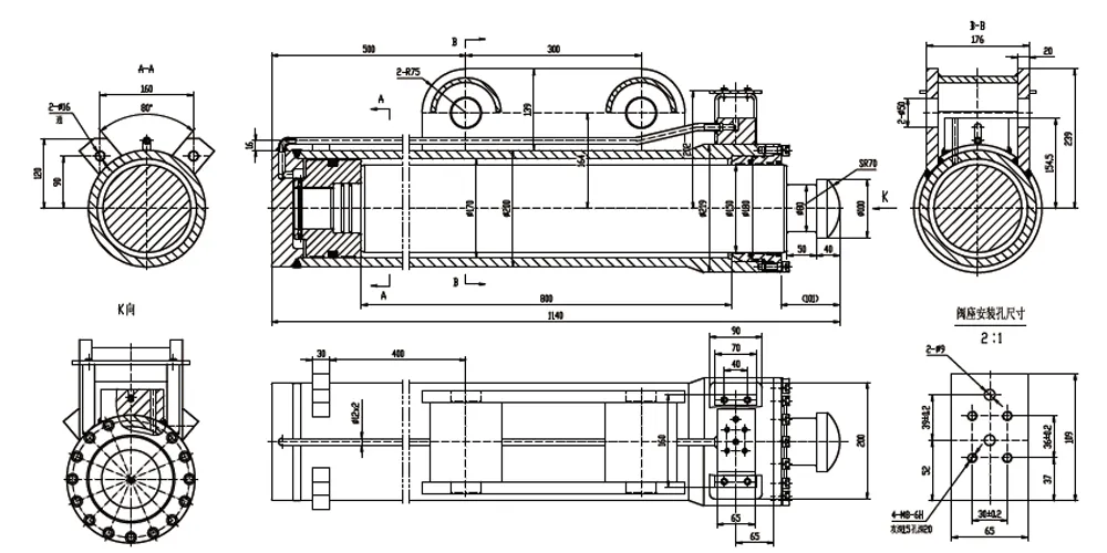
| Specifications (Bore × Rod × Stroke) | Φ170 × Φ150 × 800 mm | Bore 170 mm; Rod 150 mm (unusually large rod-to-bore ratio) |
| Working Pressure | 30 MPa | System operating pressure during frame extension/retraction |
| Maximum Withstand Pressure | 40 MPa | Proof pressure; 133% of working pressure safety factor |
| Stroke (Trip) | 800 mm | Full travel from transit-width to working-width frame position |
| Installation Distance | 1140 mm | Flange face to rod-end pin centre; fully retracted |
| Weight | 262 kg | Mechanical handling required; crane or forklift for installation |
| Bore Diameter | Φ170 mm (H8 tolerance) | Honed bore; Ra ≤ 0.4 µm; seamless steel tube |
| Piston Rod Diameter | Φ150 mm (h6 tolerance) | Hard chrome plated; Ra ≤ 0.2 µm; 42CrMo4 or equivalent |
| Annular Clearance (each side) | 10 mm | Very high rod-to-bore ratio; optimized for compressive load bearing |
| Extension Force (cap side, theoretical) | ≈ 680 kN at 30 MPa | Based on full bore area π/4 × 170² × 30 |
| Retraction Force (rod side, theoretical) | ≈ 150 kN at 30 MPa | Small annular area π/4 × (170²-150²) × 30; by design for this application |
| Cap End Attachment | Integrated structural flange plate | Welded flange with multiple bolt holes; direct connection to crane frame |
| Rod End Attachment | Clevis fork; heavy-duty forged | Pin-mounted to crawler track frame structural lug |
| Seal Compound | NBR (standard) / FKM (option) | ISO VG 46/68 oil compatible; FKM for -40°C alpine crane operations |
| Operating Temperature | -20°C to +80°C | Specify FKM seals for operations below -20°C |
2. About Our Φ170×Φ150×800 Cylinder for Frame Support
The EP-Φ170×Φ150×800 is a purpose-built cylinder for frame support engineered for the structural locking and frame expansion mechanisms of crawler crane undercarriage systems. Crawler cranes — the heavy lifting workhorses of French infrastructure construction, bridge erection, nuclear plant maintenance, and offshore petrochemical facility projects — rely on this cylinder for frame support to position, lock, and maintain the lateral width of the crawler track frames during crane setup and operational loading. This cylinder for frame support has a 170 mm bore diameter and 150 mm piston rod diameter that represent an unusual specification: the very small difference between bore and rod dimensions (only 10 mm annular clearance on each side) is characteristic of a cylinder for frame support designed primarily for compressive load-bearing rather than the typical force-generation role of standard double acting cylinders.
The 800 mm stroke of this cylinder for frame support covers the travel required to extend the crawler track frame from its narrowed transit configuration to its full working width — a repositioning movement that determines the crane's stability base during lifting operations. The 1140 mm installation distance between mounting pin centres defines the spatial envelope of the cylinder for frame support within the crane's frame structure, where space constraints are severe given the density of structural steelwork, crawler travel drives, and electrical cabling that occupy the same zones. At 262 kg, this cylinder for frame support is a substantial structural component that requires mechanical handling for installation and removal, and its specification — particularly the 40 MPa maximum withstand pressure — reflects the critical nature of the frame support function in crane stability management.
For French crane operators and maintenance companies serving the construction sector in Paris, Lyon, Nantes, and France's major infrastructure corridors — the A89 and A45 motorway projects, the Grand Paris Express extension program, and the ongoing nuclear facility maintenance at EDF's power stations along the Loire, Rhône, and Garonne river corridors — the availability of a correctly specified cylinder for frame support with complete technical documentation is a critical procurement requirement. Crawler cranes cannot work at rated capacity with incorrect or degraded cylinder for frame support units, and the consequences of frame support hydraulic failure during a lift are classified as catastrophic risk under French crane safety regulations.
3. Five Key Product Advantages
The 40 MPa maximum withstand pressure of this cylinder for frame support exceeds the 30 MPa working pressure by 33%, providing the structural safety margin demanded by crawler crane engineering standards and FEM (Fédération Européenne de la Manutention) crane design rules for safety-critical structural locking components. In crane frame support applications, the cylinder for frame support is not merely an actuator — it is a structural member that must sustain compression loads from the crane's stabilization base during lifting operations at rated capacity, while simultaneously resisting dynamic loads from wind, load swing, and ground settlement. The 40 MPa withstand rating confirms that the cylinder for frame support barrel, end caps, and attachment welds can sustain the peak loads that arise in these combined loading scenarios without yielding, and this rating is verified on every unit during the mandatory proof-pressure test before dispatch.
The 150 mm piston rod diameter — leaving only 10 mm of annular clearance on each side between the rod and the 170 mm bore — is the most distinctive engineering feature of this cylinder for frame support. This unusually large rod-to-bore ratio reflects the primary function of the cylinder for frame support as a compressive structural member: when the frame is in its working position, the cylinder for frame support locks at the extended length and must sustain the full weight and dynamic load of the crane's operating base through the rod in compression. A standard actuator cylinder optimizes bore area for force generation; a cylinder for frame support optimizes rod diameter for buckling resistance and compressive load capacity. The 150 mm rod diameter provides substantial Euler column safety factor against buckling under the compressive loads transmitted through the frame structure.
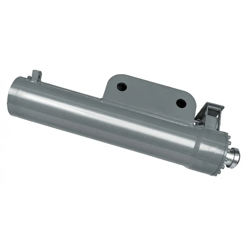
The cap-end integrated mounting flange on this cylinder for frame support — visible in the product rendering as the rectangular plate with drilled bolt holes welded to the cylinder body — provides a direct, high-stiffness connection between the cylinder for frame support and the crawler crane's structural frame members. This integrated design transfers the frame expansion and locking loads through a large bearing surface into the crane's box-section steel structure without the stress concentrations that pin-only mounting would create at the load introduction point. For crane applications where the cylinder for frame support must transmit not only axial compression but also lateral and bending loads from ground unevenness and wind loading on the crane structure, the flanged end connection provides the multi-axis load path stiffness that a simple clevis pin cannot achieve.
The 800 mm stroke of the cylinder for frame support covers the complete range of frame width adjustment from the narrowed transit configuration — where the crawler track frames must fit within legal road transport width limits — to the maximum working width that provides the crane's rated stability base for heavy lifting. On large crawler cranes deployed at French nuclear plant maintenance operations and major infrastructure bridge projects, this width adjustment is a critical setup step that determines the crane's rated capacity table: a narrower track width reduces the permissible load at any given radius, and only the fully extended cylinder for frame support position allows the crane to lift at its maximum rated capacity. This 800 mm stroke cylinder for frame support mechanizes the setup adjustment, replacing the manual pin repositioning procedure that older crane designs required and reducing setup time from hours to minutes.
The threaded gland visible at the rod entry end and the rod-end connection geometry (clevis fork accepting a structural pin) of this cylinder for frame support are precision-machined to maintain cylinder axis alignment with the crane frame's structural load path during the full extension and retraction cycle. Misalignment between the cylinder for frame support axis and the load path introduces bending moments into the cylinder rod and gland that accelerate wear and can cause gland seal failure. The precision machined mating faces and the threaded gland retention system on this cylinder for frame support maintain the load path geometry required for the cylinder to function as a structural member rather than a pure actuator, consistent with crawler crane structural design standards and the FEM 1.001 crane design rules applied to French-market cranes.
4. Working Principle of the Crawler Crane Frame Support Cylinder
The cylinder for frame support in a crawler crane operates in two distinct functional modes during the crane's working life: an active hydraulic actuation mode during crane setup and configuration changes, and a passive structural load-bearing mode during actual lifting operations. Understanding both modes is essential for correct specification, maintenance, and replacement planning of the cylinder for frame support.
During active mode — crane setup at a new work site — the hydraulic cylinder support frame mechanism receives pressurized oil at up to 30 MPa from the crane's hydraulic power unit through dedicated control valves in the undercarriage hydraulic circuit. With the crawler track frame released from its transport locking pins, the cylinder for frame support extends through its 800 mm stroke, pushing the crawler frame outward from the crane body to the desired working width. The hydraulic control system coordinates the extension of the cylinders for frame support on both sides of the crane simultaneously or sequentially, maintaining the crane body level during the width adjustment. Once the target width is reached, the hydraulic pressure locks the cylinder for frame support in position and mechanical locking pins are inserted through the frame structure to transfer the load to the structural steelwork — relieving the cylinder for frame support seals from long-term static pressure exposure that could cause seal creep or leakage during extended working periods.
During passive mode — lifting operations — the mechanical locking pins carry the primary structural loads, with the cylinder for frame support serving as the secondary load path that prevents frame width variation within the clearances of the mechanical locks. In this mode, the cylinder for frame support role is structural rather than hydraulic: it must sustain compressive, tensile, and bending loads transmitted through the frame system without dimensional change. The 40 MPa maximum withstand pressure and the large rod diameter of 150 mm are sized for this structural role of the cylinder for frame support, not just for the hydraulic actuation function. French crane engineers working to FEM 1.001 and EN 13000 crawler crane standards account for both operating modes in the cylinder for frame support specification, verifying that the hydraulic actuation capacity is adequate for the frame extension task and that the structural load capacity (determined by barrel wall strength and rod buckling resistance) is adequate for the passive structural role during lifts at rated capacity.
5. Materials and Structural Construction
The EP-Φ170×Φ150×800 cylinder for frame support uses a material specification driven by two demanding requirements that are not typically present simultaneously in standard actuator cylinders: the need to sustain hydraulic pressure at 30 MPa working pressure and 40 MPa maximum withstand pressure in the actuation mode, and the need to function as a structural compression member carrying crane frame loads in the passive mode. The cylinder for frame support barrel is produced from seamless cold-drawn steel tube conforming to EN 10305-1 specification, with wall thickness calculated to satisfy the 40 MPa proof pressure requirement while also carrying the longitudinal compressive and bending loads of the structural role. The barrel wall at the 170 mm bore must be substantially thicker than a standard 30 MPa cylinder barrel to address both requirements simultaneously.
The 150 mm piston rod of this cylinder for frame support is produced from 42CrMo4 alloy steel (EN 10083 specification) quench-and-tempered to achieve a core tensile strength of minimum 1000 MPa. At this rod diameter, the Euler buckling criterion is not limiting for the 800 mm stroke — the critical buckling load for a 150 mm diameter rod at 800 mm unsupported length is orders of magnitude higher than the applied axial loads. The buckling resistance is designed in for longer rod exposure during the extension transition, and the 150 mm diameter provides generous safety factor. After precision machining to h6 tolerance, the cylinder for frame support rod receives hard chrome plating to a minimum 0.030 mm depth, ground and polished to Ra ≤ 0.2 μm. At this large rod diameter, the chrome deposit volume is substantial and the long-term durability of the chrome surface against the fretting and micro-movement loads associated with the passive structural role is an important quality parameter verified during production inspection.
The cap-end integrated flange of the cylinder for frame support is a structural welded assembly joining the cylinder barrel to the mounting plate. The weld joints in this assembly carry combined axial tension or compression, bending moments, and shear forces depending on the loading scenario — a multiaxial stress state that requires weld quality classification to EN 1090 or equivalent structural steel fabrication standard. The weld joint geometry, procedure qualification, and inspection requirements for this assembly should be documented in the cylinder's technical file, which we provide with qualifying orders for crane application customers who require this documentation for their crane design technical file under EN 13000. The rod-end clevis fork of this cylinder for frame support is machined from forged steel billet, providing the grain structure refinement and uniform mechanical properties that castings or fabricated alternatives cannot match at this load level.
6. Cylinder for Frame Support — Selection and Procurement Guide
Selecting the correct cylinder for frame support for a crawler crane undercarriage system requires verifying five parameters from the original equipment specification: bore diameter, rod diameter, stroke, installation distance, and cap-end attachment geometry. For the HCYY11112020 cylinder for frame support, these are Φ170 mm bore, Φ150 mm rod, 800 mm stroke, 1140 mm installation distance, and an integrated flange mounting plate. A replacement cylinder for frame support that matches bore, rod, and stroke but has a different installation distance will place the frame pins out of alignment at the design working width — requiring either mechanical shimming or frame bracket modification before the cylinder for frame support can be used safely.
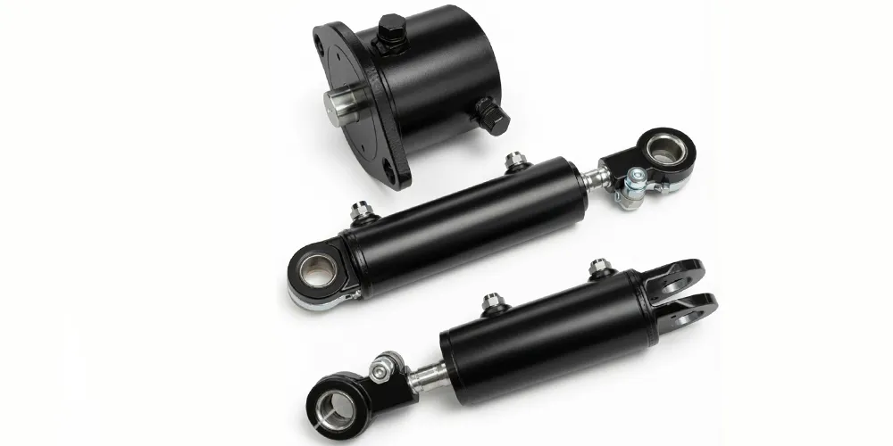
When comparing the cylinder for frame support with lower rod-to-bore ratio alternatives, the critical functional difference is compressive load capacity. A standard actuator cylinder with a Φ80 mm or Φ100 mm rod in a Φ170 mm bore generates a higher rod-side retraction force — useful in general actuator applications — but carries significantly less axial compressive load in the structural locking mode than the cylinder for frame support with its Φ150 mm rod. For crawler crane applications where the cylinder for frame support must carry the crane's stability loads during lifts, substituting a standard actuator cylinder for a genuine cylinder for frame support with the correct rod diameter compromises the structural safety of the crane system and would fail EN 13000 design verification for the luffing and stability calculation.
As a specialist hydraulic cylinder manufacturer serving the French and European crane market, we supply the cylinder for frame support with a complete EN 13000-compatible documentation package. French crane operators who use this cylinder for frame support in maintenance operations at EDF nuclear facilities or in construction projects requiring lift plan certification should specify the documentation package at time of order. Contact our cylinder for frame support technical team with the crane model designation, existing cylinder serial number, and required certification scope for a confirmed cross-reference and quotation.
7. Application Scenarios
The EP-Φ170×Φ150×800 cylinder for frame support serves the crawler frame expansion, width locking, and structural support functions across multiple crane categories and heavy lifting applications in France and across Europe. Below are the primary deployment scenarios where this cylinder for frame support specification is commonly required.
Large crawler cranes deployed at French construction sites — road and bridge projects under APRR and SANEF motorway programs, high-rise building construction in Paris La Défense and Lyon Part-Dieu, and industrial plant installation projects — must be transported on public roads in a narrowed configuration where the crawler track frames are positioned close to the crane body to meet the 2.55 m or 3.0 m maximum width limits of the vehicles under the Arrêté du 2 mars 2022 on vehicle dimensions. At the work site, the cylinder support frame mechanisms extend the track frames to the full working width that provides the rated stability base for the crane's lifting capacity table. The 800 mm stroke of this cylinder for frame support covers this transition for crawler cranes in the 250 to 600 tonne capacity class that commonly use this cylinder for frame support specification.
EDF's 56 operating reactors across France — distributed along the Loire, Rhône, Garonne, Rhine, and Seine river corridors — require periodic heavy lifting operations for reactor head removal, steam generator replacement, and heavy component handling during planned outages. These operations use large crawler cranes positioned within the confined spaces of the nuclear island where precise frame width control determines whether the crane can access the lifting positions. The cylinder for frame support used in nuclear facility crane operations must carry documentation demonstrating material traceability and qualification testing, as nuclear safety regulations (ASN — Autorité de Sûreté Nucléaire) impose quality assurance requirements on all equipment entering controlled zones of nuclear facilities.
French port expansion projects at Le Havre Grand Port Maritime, Marseille-Fos, and Nantes-Saint Nazaire deploy large crawler cranes for quay wall construction, jetty installation, and offshore structure assembly. These marine environments impose corrosive conditions on all mechanical components — salt spray, tidal humidity, and marine organism fouling — that accelerate chrome rod corrosion and seal degradation in cylinder support systems that are not properly maintained. The cylinder for frame support on marine-deployed crawler cranes requires additional inspection frequency, chrome rod protective sleeve covers when not in use, and corrosion-resistant sealing compounds that maintain their properties across the temperature and humidity cycling characteristic of French Atlantic and Mediterranean coastal environments.
Major French bridge and viaduct projects — including ongoing maintenance and construction on the A75 Millau viaduct approach structures, the Seine crossings in the Paris region, and the Grand Paris Express station construction — use crawler cranes for segment placement, bearing installation, and structural steel erection at heights and spans where the crane's stability base is critical for both equipment safety and structural accuracy. The cylinder frame support mechanism's precision control of track frame width allows crawler cranes to position themselves accurately within the narrow access margins at bridge pier locations, and the locking function ensures that the stability base geometry is maintained precisely throughout the lift cycle as required by the crane lift plan approved under French construction site safety planning regulations. The cylinder for frame support is the key enabling component in this precision positioning.
French chemical, petrochemical, and industrial gas facilities — including Total Energies refineries at Donges and Gonfreville, Air Liquide production installations, and Arkema chemical plants — require periodic large-component replacement and new equipment installation that uses crawler cranes for column, vessel, and reactor handling. These indoor and semi-indoor industrial environments limit crane movement and require precise track frame width adjustment to access lifting positions between existing process equipment and pipe racks. The cylinder for frame support mechanism's ability to fine-position the track frame width to the available aisle dimension — rather than choosing between only a few fixed positions — provides the operational flexibility that plant turnaround scheduling requires.
88. Regulatory Standards and Compliance — France and Europe
EN 13000 specifies design, stability, and safety requirements for mobile cranes including crawler cranes. Hydraulic cylinders used in safety-critical structural functions — including the frame support and outrigger systems — must be designed and tested to the requirements implied by the crane's rated capacity and stability calculations. The standard requires that structural components including the cylinder support system be verified by calculation and by proof testing to the design load with appropriate safety factors. Replacement cylinder for frame support units must maintain the design parameters used in the original crane's EN 13000 conformity assessment, and the technical documentation provided with this cylinder for frame support supports this requirement.
Crawler cranes operating in French workplaces are subject to the periodic inspection requirements of the Arrêté du 1er mars 2004, which classifies lifting equipment requiring annual full technical inspection (vérification générale périodique) by a qualified body. The frame support hydraulic system — including the cylinder for frame support — is a safety-critical element that must be specifically verified at each inspection for hydraulic integrity, seal condition, correct operation, and structural attachment condition. The inspection findings and any replacement component data must be recorded in the crane's inspection logbook (carnet de maintenance), which is retained with the equipment throughout its service life.
FEM 1.001 provides the load classification, duty cycle, and design criteria used for crane structural design across Europe. The cylinder for frame support falls within the FEM structural component classification system, which assigns component service life requirements based on the load spectrum and cycle count during the crane's design life. The cylinder for frame support design must satisfy FEM fatigue life requirements for the expected number of frame width adjustment cycles over the crane's inspection interval, ensuring that structural fatigue rather than hydraulic seal wear is not the limiting failure mode. FEM 1.001 is referenced in EN 13000 and is therefore applicable to all crawler cranes placed on the French market.
ISO 4413 applies to all hydraulic systems including the crawler crane undercarriage hydraulic circuit that supplies the cylinder for frame support. The standard's requirements on pressure rating with appropriate safety factors — consistent with this cylinder for frame support's 40 MPa withstand at 30 MPa working pressure — and on system protection against over-pressure events are directly applicable. For crane applications specifically, ISO 4413's requirements on load-holding valve design (counterbalance or holding valves to prevent uncontrolled frame movement if a hydraulic hose fails) are safety-critical provisions that the crane hydraulic system designer must address for any cylinder support frame hydraulic circuit.
The integrated flange weld assembly of this cylinder for frame support falls under the scope of EN 1090 structural steel fabrication standards when the cylinder for frame support is classified as a structural component in the crane's technical file. EN 1090 specifies execution class requirements for weld procedure qualification, welder qualification, non-destructive testing, and dimensional tolerance that apply to welded structural components in CE-marked structures. For crane applications in France where the cylinder for frame support is classified as a structural element, EN 1090 compliance documentation — weld procedure records, welder certificates, NDT inspection records — should be included in the cylinder for frame support technical file provided to the crane operator.
9. Compatible Hydraulic System Products
Crawler crane hydraulic systems integrate multiple cylinder types within a common power unit circuit. We supply compatible industrial hydraulic cylinders across the full range of crane and lifting equipment applications for one-stop procurement in France and across Europe.
Our range of tilt cylinders covers the blade and mast tilt applications in the same heavy equipment categories that deploy a cylinder for frame support — excavators, pushers, and heavy plant where a controlled tilt function works alongside the cylinder for frame support or outrigger extension system in the same hydraulic circuit. For companies managing crane and heavy equipment fleets in France, our cylinder range covers multiple function positions within the same equipment family, simplifying supplier qualification, spare parts stockholding, and maintenance documentation management across the fleet.
The forklift lifting cylinder range shares manufacturing standards, quality documentation practices, and pressure rating methodology with the cylinder for frame support series. For French crane operators and industrial facilities that also manage forklift fleets for on-site material handling — a common combination at large construction sites and industrial plants — single-vendor procurement for all hydraulic cylinder types reduces the procurement overhead and provides a consistent standard of technical documentation across the full cylinder inventory. We supply lifting cylinders across the full range of forklift capacities from 1.5 to 8 tonnes.
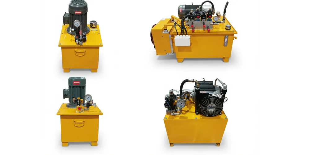
The hydraulic pump station that supplies the crawler crane undercarriage cylinder for frame support must deliver 30 MPa working pressure with adequate flow rate for acceptable frame extension cycle time. We supply matched pump stations for crane undercarriage applications with documentation confirming compatibility with the HCYY11112020 cylinder for frame support port specification, pressure rating, and flow volume requirements. For crane operators procuring complete hydraulic system replacements during major crane refurbishment — a common activity during planned maintenance for EDF nuclear site cranes and port crane fleet upgrades in France — our matched pump station and cylinder for frame support packages provide pre-verified system compatibility.
10. About Us
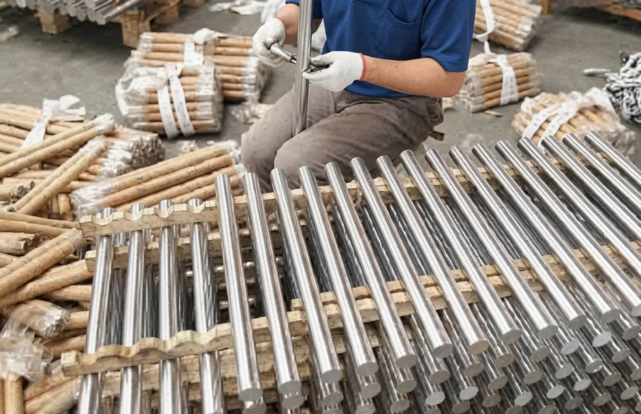
As a specialist hydraulic cylinder manufacturer, we produce heavy industrial actuators and structural hydraulic cylinders across a broad specification range — from compact steering cylinders for aerial work platforms through large-bore, long-stroke swing arm cylinders for refuse vehicles and the extreme-specification cylinder for frame support units for crawler cranes described on this page. Our production capability includes deep-hole boring for large-bore barrel production, CNC precision honing for bore surface finish, large-diameter chrome plating lines, structural welding qualified to EN 1090, and high-pressure test benches capable of verifying the 40 MPa maximum withstand pressure specified for this cylinder for frame support. ISO 9001 quality management certification covers the complete manufacturing process.
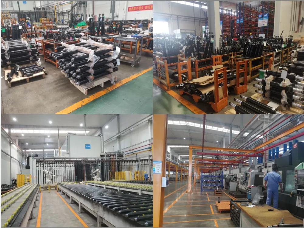
WorkShop
Frequently Asked Questions
Editor: PXY