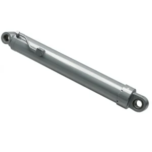
Silinder Sudut Boom Utama EP-Φ70×Φ40×555 untuk Kendaraan Kerja Udara
1. Technical Specifications
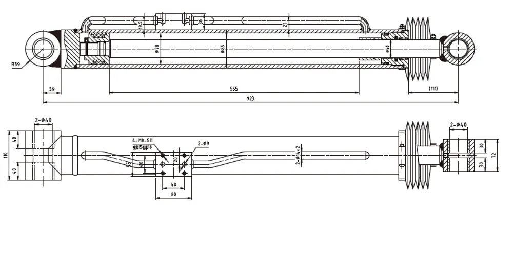
Complete dimensional and performance parameters for the EP-Φ70×Φ40×555 main boom angle cylinder as supplied for aerial work vehicle applications.
| Parameter | Value | Notes |
|---|---|---|
| Cylinder Model | HCYY11112010 | EP Series Main Boom Angle |
| Specifications (Bore × Rod × Stroke) | Φ70 × Φ40 × 555 mm | Double acting |
| Working Pressure | 20 MPa | Continuous rated |
| Maximum Withstand Pressure | 30 MPa | Proof / test pressure |
| Stroke (Trip) | 555 mm | Full boom angle travel |
| Installation Distance | 923 mm | Pin-to-pin retracted |
| Weight | 28 kg | Fully assembled |
| Bore Diameter | Φ70 mm | Honed, H7 tolerance |
| Rod Diameter | Φ40 mm | Hard chrome plated |
| Theoretical Extension Force | ≈ 76.9 kN | At 20 MPa rated pressure |
| Mounting Configuration | Clevis / Clevis | Both ends pinned |
| Counterbalance Valve | Integrated / Available | Load-holding safety function |
| Operating Temperature Range | −25 °C to +80 °C | Mineral hydraulic oil |
| Actuation Type | Akting Ganda | Powered extend and retract |
| Application | Aerial Work Platform | Main boom lift function |
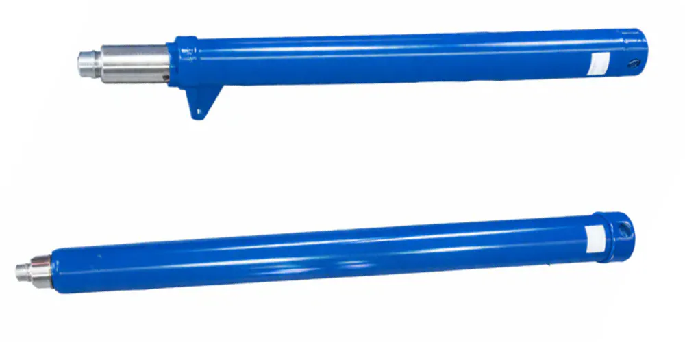
2. What Is a Main Boom Angle Cylinder?
A main boom angle cylinder is the primary lifting actuator responsible for raising and lowering the main boom section on an aerial work platform, boom lift, or cherry picker. Mounted between the turntable and the underside of the boom, this large-bore hydraulic ram converts pump flow into the rotational lifting force needed to swing the boom through its full angular range — from fully stowed at ground level to maximum elevation, often exceeding 70 degrees above horizontal. Unlike the smaller leveling and offset cylinders elsewhere on the machine, the main boom angle cylinder carries the full structural load of the boom, the platform, and the rated working load, making it the single most heavily stressed hydraulic component on the entire vehicle.
For boom lift manufacturers and fleet operators across France and the broader European market, selecting a main boom angle cylinder that is correctly rated for working pressure, stroke, and structural fatigue life is not optional — it is the foundation on which the entire machine's safe working load rating depends. The EP-Φ70×Φ40×555 unit covered on this page is built specifically for this duty, with a bore diameter, rod size, and stroke length calibrated to the angular geometry and load requirements typical of mid-size to large articulating boom platforms used in construction, utility maintenance, and infrastructure inspection work.
Because the main boom angle cylinder operates continuously through thousands of lift cycles over a machine's service life, its sealing system, rod surface treatment, and barrel honing quality directly determine how long the cylinder will perform before requiring overhaul. Every detail in the specification that follows reflects the demands of this duty cycle, from the 30 MPa proof pressure rating down to the precise chrome plating thickness on the piston rod.
3. Five Key Advantages of the EP Main Boom Angle Cylinder
What sets this main boom angle cylinder apart from generic boom cylinder alternatives in the aerial work platform market.
1. Large Φ70 Bore for High Lifting Force
At Φ70 mm bore diameter and 20 MPa rated working pressure, this main boom angle cylinder generates approximately 76.9 kN of theoretical extension force — sufficient margin to lift the boom, platform, and rated payload through the full angular travel without operating near the cylinder's mechanical limit during normal duty cycles.
2. 555 mm Stroke Matched to Boom Geometry
The 555 mm stroke of this main boom cylinder is precisely sized to deliver the full angular sweep required on mid-to-large articulating boom platforms, converting linear extension into the rotational lift that raises the boom from stowed transport position to maximum working elevation without any intermediate linkage compromise.
3. 30 MPa Proof Pressure Safety Margin
With a 20 MPa continuous working pressure and a 30 MPa maximum withstand pressure, this main cylinder is built with a 50% pressure safety margin above rated load — protecting against the dynamic pressure spikes generated by sudden boom stop, wind gust loading, and uneven ground conditions encountered on real construction sites.
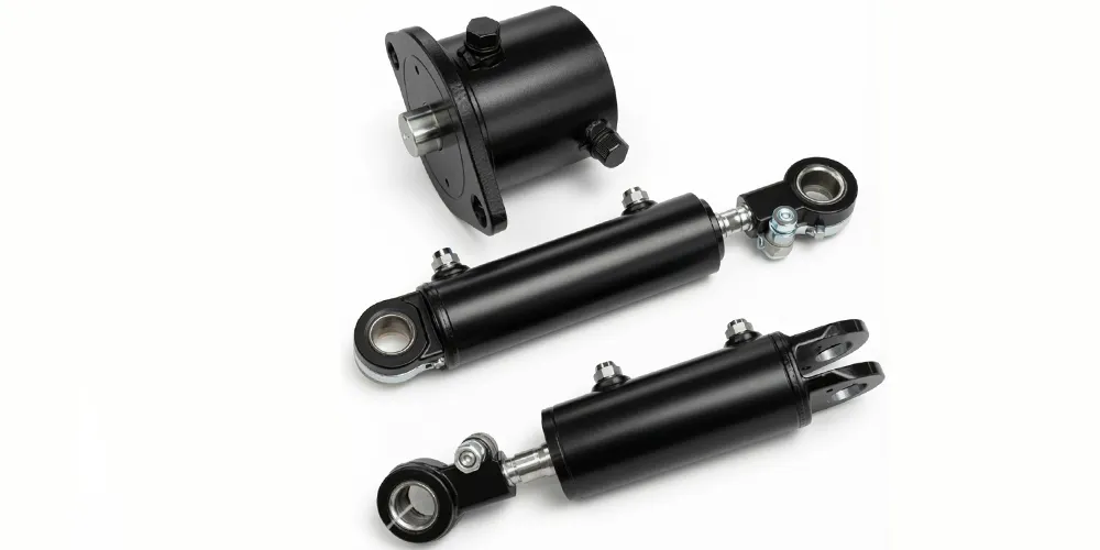
4. Robust Clevis Mounting at Both Ends
Both the base and rod-end clevis fittings on this main boom angle cylinder are sized for the high bending and shear loads transmitted through the boom pivot connection, with bearing bore diameters and pin engagement lengths calculated to resist the fatigue cracking that undersized clevis designs experience after repeated full-load lift cycles.
5. 28 kg Weight-Optimised Steel Construction
At 28 kg fully assembled, this main boom angle cylinder achieves a favourable strength-to-weight ratio that keeps unsprung structural mass at the boom pivot low — reducing the inertial load the turntable slew bearing and counterweight system must manage during boom acceleration and deceleration phases of the lift cycle.
4. How Does the Main Boom Angle Cylinder Work?
The main boom angle cylinder is connected mechanically between a fixed pivot point on the turntable and a moment-arm bracket on the underside of the boom structure. When the operator commands boom-up movement from the platform or ground controls, the directional control valve routes pressurised hydraulic fluid into the base-side (cap-end) chamber of the cylinder. As oil fills this chamber, the piston rod extends, and because the rod end is pinned to the boom's lifting bracket at a fixed moment-arm distance from the boom's own pivot point, the linear extension of the cylinder is converted into rotational movement of the boom about its pivot — raising the boom angle progressively as the rod extends through its 555 mm stroke.
Lowering the boom reverses this flow path: hydraulic fluid is directed into the rod-side chamber while the cap-end chamber is allowed to return to tank, retracting the piston rod and rotating the boom back down toward the stowed position. Throughout both extension and retraction of the main boom angle cylinder, a counterbalance valve mounted directly on or near the main boom angle cylinder maintains controlled lowering speed even if a hose ruptures or hydraulic pressure is lost — a critical safety function given the substantial overturning moment the elevated boom and platform represent. This load-holding capability of the main boom angle cylinder is what distinguishes the main boom angle cylinder from a simple single-function hydraulic ram.
Because the main boom angle cylinder must hold position under load for extended periods — for example while a worker is stationary at height performing maintenance or inspection tasks — internal leakage past the piston seal is held to extremely tight tolerances. A properly functioning main boom angle cylinder will show negligible drift in boom angle over a sustained holding period of 10 minutes or more under full rated load, a performance characteristic that is directly verified during factory acceptance testing before the cylinder is approved for shipment.
5. Materials and Construction
As the primary structural lifting member on the boom, a main boom angle cylinder must be built from materials that combine high tensile strength, fatigue resistance under cyclic loading, and corrosion resistance for outdoor service across France's varied climate zones — from coastal humidity to inland temperature extremes. Every component is specified to withstand the full duty cycle demands of continuous commercial boom lift operation.
Cylinder Barrel
Cold-drawn seamless steel tube (27SiMn or equivalent high-strength alloy) honed to Ra 0.4 µm internal finish. The higher-strength alloy specification for this main boom cylinder reflects the elevated hoop stress generated at 30 MPa proof pressure in a Φ70 bore barrel compared to smaller-bore cylinders elsewhere on the machine.
Piston Rod
40Cr alloy steel, induction-hardened to 50–55 HRC surface hardness and chrome-plated to 25–30 µm hard chrome thickness, then precision-ground to Ra 0.2 µm. The thicker chrome specification on this Φ40 rod accounts for the greater exposure to weather and site contamination during extended outdoor boom-lift duty cycles in France.
Clevis End Fittings
Forged 45# steel clevis ends, normalised and stress-relieved after machining, with pin bores reamed to H7 tolerance for accurate, low-wear pin fit. The forging process — rather than simple casting — gives the clevis grain structure the directional strength needed to resist fatigue cracking at the highly loaded pin bore location.
Sealing System
Polyurethane piston and rod seals with PTFE guide rings and NBR static O-rings, rated for continuous operation with mineral hydraulic oil across −25 °C to +80 °C. The seal compound selection prioritises long-term compression-set resistance, since a main boom angle cylinder holding position for extended periods relies on seal integrity rather than valve position to prevent boom drift.
Surface Protection
Epoxy primer with polyurethane topcoat on the barrel and end caps, providing salt-spray resistance exceeding 480 hours per ISO 9227 — an important specification for boom angle cylinder durability on coastal French construction sites where the main boom angle cylinder operates in marine or de-icing salt environments.
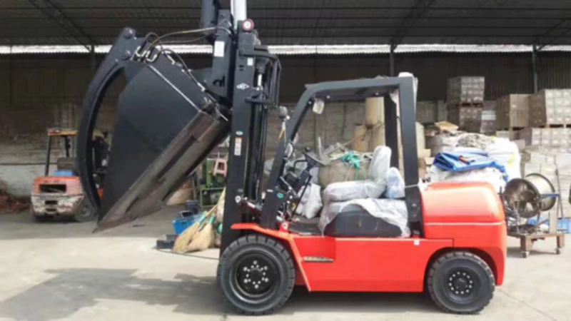
6. Application Scenarios
The main boom angle cylinder is the primary lift actuator across a wide range of aerial work platform configurations used throughout France and the European construction, utility, and infrastructure sectors.
Articulating Boom Lift
On articulating boom platforms widely used for building facade maintenance and interior construction work across French cities, the main boom angle cylinder raises the primary boom section while a separate jib or upper boom cylinder provides additional reach geometry. The 555 mm stroke of this main boom angle cylinder accommodates the full angular travel typical of mid-size articulating platforms operating in confined urban environments.
Telescopic Boom Lift
Telescopic boom platforms — favoured for long-reach construction and industrial maintenance work across French and European industrial sites — rely on the main boom angle cylinder as the sole elevation actuator while telescoping sections extend horizontal reach. The Φ70 bore of this main boom angle cylinder is sized for the higher cantilever loads generated when the boom is fully extended at maximum angle.
Cherry Picker / Bucket Truck
Utility vehicles known across France as nacelles élévatrices or camions nacelle use a cherry picker hydraulic cylinder configuration in which the main boom angle cylinder provides primary elevation for line maintenance, tree pruning, and street lighting service. The 30 MPa proof pressure rating gives ENEDIS and French municipal fleet operators the safety margin required for repeated daily lift cycles over multi-year service life.
Bridge and Infrastructure Inspection
Bridge inspection units operated by French infrastructure authorities including SNCF Réseau and regional autoroute concessionaires depend on the main boom angle cylinder to position inspectors precisely below and alongside structural elements. The counterbalance-valve load-holding function is particularly important here, since inspectors often remain stationary at extended boom angle for extended periods during detailed structural assessment work.
Warehouse and Industrial Maintenance
Indoor and outdoor industrial maintenance platforms used across French logistics and manufacturing facilities apply the main boom angle cylinder for routine access to overhead equipment, lighting, and ductwork. The compact 923 mm installation distance allows this main boom angle cylinder to fit within the constrained chassis envelope typical of compact and mid-size boom lift platforms used in facility maintenance roles.
7. Regulatory Compliance — France and European Markets
As the primary load-bearing hydraulic component on an aerial work platform, the main boom angle cylinder is subject to demanding regulatory requirements in France and across the EU. Manufacturers, OEMs, and fleet operators should verify compliance documentation before deploying equipment on regulated worksites.
EN 280:2013+A1:2015 (France / EU)
The European standard for mobile elevating work platforms requires structural calculation and proof load testing of all primary lifting cylinders, including the main boom angle cylinder. Stability criteria mandated under EN 280 directly drive the minimum bore diameter and pressure rating required for a given boom length and rated payload combination.
EU Machinery Directive 2006/42/EC
All aerial work platforms placed on the French and EU market require CE marking under the Machinery Directive, with the technical file documenting the hydraulic system including pressure ratings, counterbalance valve specifications, and burst-pressure margins for the main boom angle cylinder and all other primary hydraulic actuators.
ISO 4413: Hydraulic Fluid Power
ISO 4413 sets the general rules for hydraulic systems on mobile machinery, establishing the proof-to-working pressure ratio requirements that this main cylinder satisfies at 30 MPa proof against 20 MPa rated working pressure — a 1.5× safety factor consistent with primary lifting circuit requirements under the standard.
Code du Travail (France) — Work at Height
French labour regulation under Articles R4323-58 to R4323-91 of the Code du Travail requires periodic technical inspection of MEWPs by a qualified inspector, with the main boom angle cylinder specifically assessed for rod surface condition, seal leakage, and load-holding performance at each general periodic inspection (vérification générale périodique).
ANSI A92.20 (USA Export)
For OEMs supplying aerial work platforms to North American markets, ANSI A92.20 establishes design verification requirements for primary lift cylinders including load testing protocols that the main boom angle cylinder must satisfy before machine certification.
REACH Regulation (EC) 1907/2006
The hard chrome plating process used on the piston rod of this main boom angle cylinder is subject to REACH authorisation requirements covering hexavalent chromium compounds. Manufacturers supplying this main boom angle cylinder to French and EU customers should provide REACH compliance declarations confirming the chrome process meets current authorisation conditions.
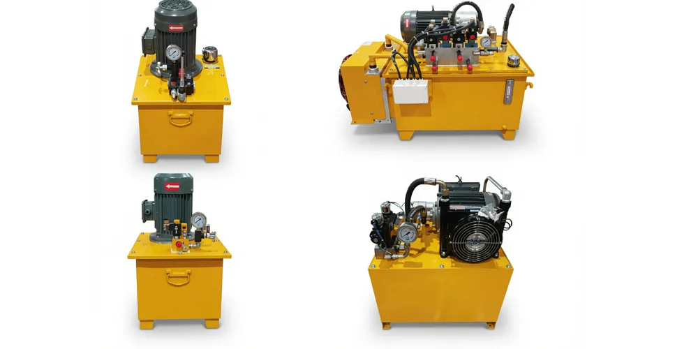
8. Related Hydraulic Products
We supply a complete range of hydraulic cylinders and components that complement the main boom angle cylinder within an aerial work platform's complete hydraulic system — giving fleet operators and OEMs a single-source supply advantage.
9. About Our Hydraulic Cylinder Manufacturing
We are a specialist hydraulic cylinder manufacturer with deep technical experience across aerial work vehicle, materials handling, and heavy industrial machinery applications. Every main boom angle cylinder we produce undergoes dimensional verification against drawing tolerances, full-pressure load testing to proof pressure, a 100% seal leak inspection, and a load-holding drift test before final approval for dispatch — providing the documented quality evidence that OEM machine builders require for their EU Machinery Directive technical files.
We supply hydraulic cylinder components to OEMs, equipment distributors, and fleet maintenance operators across France, the wider EU, and international markets. Our manufacturing facility maintains certified quality management systems covering raw material traceability through to final inspection, and our technical support team works directly with customers to confirm correct cylinder specification, replacement cross-references, and custom configuration requirements for non-standard boom geometries.
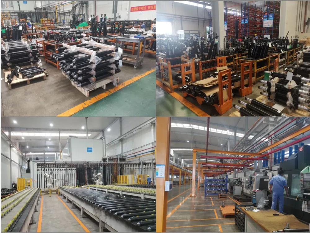
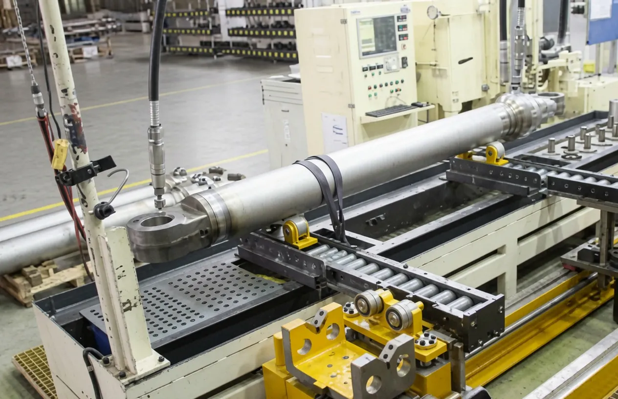
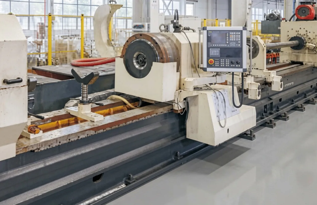
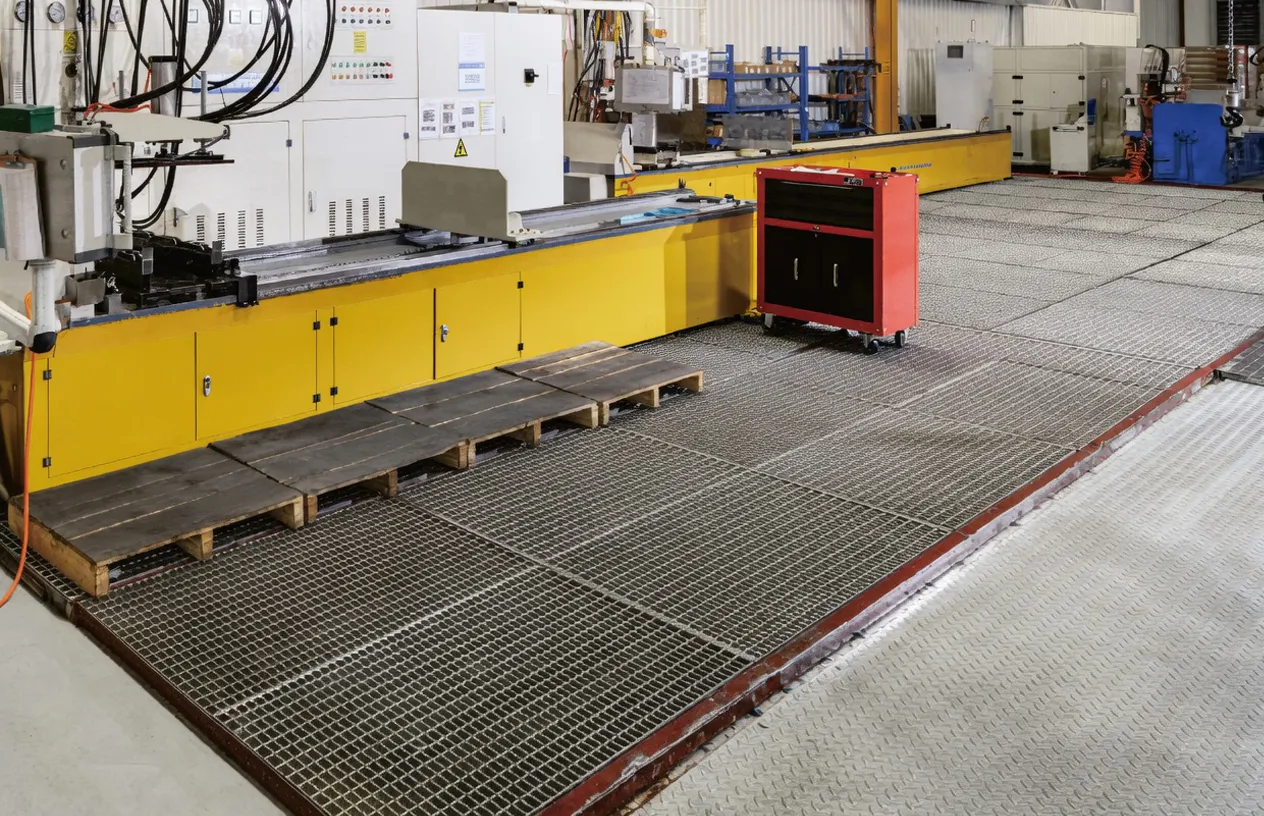
WorkShop

Frequently Asked Questions
Editor: PXY